
Service manual


S 301.01-00 7
95.11
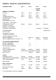
ELECTRONIC SECTION
THE DIFFERENT TYPES OF P.C.B. CARDS
Each oven can have from 2 to 3 electronic cards.
These are divided into two types:
- mother boards, with all inputs
- user interface cards
The mother boards are subdivided into the following catego-
ries:
- POW 1 as used in ISG ovens
- POW 2 as used in ovens with steam generators.
The mother board POW 2 differs from the POW 1 board for
as it features an additional series of level control relays.
The user interface boards are identified by the following
acronyms:
UIA as used in levels L2, L3
UIB as used in level L4, ACTIVE COMBI
KS as used in levels L2 (without meat probe)
PRB as used in levels L3, L4, ACTIVE COMBI
(with meat probe)
UIC as used in level L6
FSC as used in model ACTIVE COMBI
All P.c.b. cards are fitted with a “POWER FAIL” device,
which stops the cooking cycle during blackouts and contin-
ues, from the point in which it was stopped, when the power
is restored.
How to handle the P.c.b. cards
P.c.b. cards supplied as spare parts are wrapped in protective
anti-shock and antistatic material and should be left in the
protective wrapping until they are to be used.
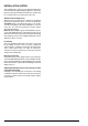
Caution! When handling the cards, apart from the meas-
ures to be taken in view of preventing their exposure to
electrostatic discharge, the utmost care must be taken in
order to avoid mechanical damage to the cards them-
selves, the components and wiring which must not be bent
and or stretched. Until the card has been installed correctly
particular care must also be taken when handling the
hermetically sealed buttons which are extremely delicate
and sensitive to even light shocks which tend to bend the
actuating pins (see fig.2) This precaution must also be
taken when extracting and inserting the extension caps
which are fitted over the pins.
Due to their high sensitivity to electronic discharge ground-
ing straps must be worn whenever you are working with the
cards or the integrated circuits. The grounding strap pincers
must be attached to the framework of the oven
Fig. 2
which should in turn be earthed. The grounding strap is
available as a spare part with the s.p.n. 02898.
REPLACING P.C.B. CARDS
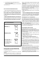
MOTHER BOARD (Fig. 3)
Foreword
When replacing a mother board the following points should
be taken into consideration:
• The position of the jumper “A” (fig.3) located near the
transformer. This jumper must be inserted between the
contacts X and Y on levels 2 and 3 and the contacts Y and
Z on levels 4 to 6 and ACTIVE COMBI.
• The memory chip “C” which carries the ovens history and
therefore the amount of operational hours and the operational
parameters which have been personalised to the customers
individual requirements by the technician.
• The microprocessor “B” where the operating parameter
reference numbers are stored. The microprocessor has an
individual acronym which identifies the version.
• On level 6 models an ulterior cooking program memory
chip is present. This chip is mounted on the UIC card above
the cooking program display. Should the POWER 2 board
be replaced the cooking program memory will not be lost.
If however the UIC card is replaced the memory chip will
have to be recovered from the old card and mounted on the
new card.
Fig. 3
Legend:
A - Jumper
B - Microprocessor
C - Memory chip
D - Computer interface connection (if required)
F
X
YZ
=
=
A
D
B
C