Your Installation Guide to Access Point Version 2.
Copyright Statement No part of this publication may be reproduced, stored in a retrieval system, or transmitted in any form or by any means, whether electronic, mechanical, photocopying, recording or otherwise without the prior writing of the publisher. Windows 95/98 and Windows 2000 are trademarks of Microsoft Corp. Pentium is trademark of Intel. All copyright reserved.
1
2
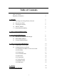
Table of Contents Table of Contents Regulatory information 3 4 1. Welcome 1.1 Advantages for Using Wireless Network 1.2 About Access Point 1.3 Verifying kit contents 1.4 Wireless Adapter 1.5 System Interoperatability 5 5 6 6 6 6 2. Step-by-Step Installation Guide 7 3. Access Point SNMP Manager 3.1 About Access Point SNMP Manager 3.2 Install SNMP Manager 3.3 Uninstall SNMP Manager 8 8 9 13 4. Using Access Point SNMP Manager 4.1 Connecting to Access Point 4.2 Configuring the Access Point 4.2.
Regulatory Information The manufacturer is not responsible for any radio or television interference caused by unauthorized modification of this device or the substitution or attachment of connecting cables and equipment other than specified. The correction of interference caused by such unauthorized modification, substitution or attachment will be the responsibility of the user.
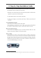
1. Welcome Thank you for purchasing Access Point! Access Point is easy to install and easy to operate—in no time you will have your own wireless network. This guide will lead you through the installation process in detail. Please read this manual carefully and keep it for future reference. You need to have a basic knowledge of installation procedures for network operating systems under Microsoft Windows 95 (or up) and Windows NT. 1.
1.2 About Access Point The Access Point is a modular unit with an integrated Ethernet interface that enables you to use your Access Point with your adaptors. The Antennas are built-in which creates further wireless atmosphere and a cleaner look. The Access Point is a wired to wireless bridge that you can use to connect wireless cells to one another or to a wired (Ethernet) Local Area Network. The Access Point can serve mobile wireless clients roaming between various locations within network premises. 1.
2. Step-by-Step Installation Guide This section helps you with the installation of the Access Point. the instructions on how to install your Access Point: Please follow 1. Mount the Access Point firmly to the wall on the desired position. A drill model is supplied as a separate sheet with this manual. 2. Connect Ethernet cable to Access Point’s RJ-45 Port 3. Connect power adapter to Access Point, and “Power” LED of Access Point will turn green.
3. Access Point SNMP Manager 3.1 About Access Point SNMP Manager Access Point SNMP Manager allows users to view contents of all wireless networks under Windows system (e.g. how many Access Points there are in a WLAN). You can use it to control a large number of IEEE 802.11b Access Points from a single location. Further more, the Access Points are remotely updated through the SNMP automatically. All indicate a simpler management for your wireless LAN.
3.2 Step 1. Install SNMP Manager To Install Access Point SNMP Manager, please insert CD containing SNMP Manager into one computer of the LAN. Wait a few seconds for the screen below to show up. Click Next. If InstallShield Wizard window doesn’t display, please go to ‘My Computer’ and double click on CD-ROM drive. Run “Setup.exe”.
Step 2. Read the License Agreement and click Yes if you accept the terms. Step 3. Choose Destination Location. Click Browse to choose a destination folder and click “Next” to install AP Configuration.
Step 4. Select Program Folder: Type a new folder name or select one from the Existing Folders list. Click “Next”. Step 5. Start Copying Files: Review the settings before copying files. click “Back” to make changes. Click “Next” to star copying.
Step 6. Congratulations, AP Configuration is successfully installed! Click “Finish”. Step 7. You have to restart your computer. Choose to restart now or later. “Finish”.
3.3 Uninstall SNMP Manager Step1. Click Start>Programs>IEEE802.11b WLAN Utilities>AP Configuration>Uninstall AP Configuration. Select “Remove” and Click “Next” Step 2. Click “Yes”. Yes Step 3. Uninstallation is complete. Cancel Click “Finish”.
4. Using Access Point SNMP Manager 4.1 Connecting to the Access Point z Follow the steps to connect to the Access Point: Step 1. On the Start Menu, click Start>Programs>IEEE802.11b WLAN Utilities>AP Configuration>AP Configuration. Step 2. On the File Menu, click File>Find Access Point. see the list of all available Access Points. Step 3. Select one Access Point and click on it’s Name and click Connect or simply double click on the Name. Step 4.
Step 5. When the chosen Access Point is found, click “OK” OK If the designated Access Point is not found, an error message appears. Click “OK” and try to find another Access Point. OK Note! Step 6. You may ping the Access Point to see if the Access Point has the correct IP address and is connected to the network properly. If you want to exit Access Point SNMP Manager, select File>Exit. z To view the version of the Access Point SNMP Manager, click Help>About SNMP Manager.
4.2 Configuring the Access Point Once the connection has been completed, you can see two messages in the bottom of the window. The one in the left indicates “Get Configuration done”; the other one in the right display the IP address of the connected Access Point. 4.2.1 Setting the IP address of the Access Point To set the IP address of the Access Point, follow the steps: Step 1. Step 2.
z Options: Indicates the polling interval according to which the SNMP Manager polls the Access Point in order to update the statistics and the Associated Stations List. The default value is 0 seconds. z Exit: Exits Access Point SNMP Manager. 4.2.3 Setup Menu z IP Configuration: Click Setup>Bridge>IP Configuration. If you modify any settings in this window, don’t forget to save them by clicking File>Download Changes. 1. MAC Address: Stands for Media Access Control.
4. 5. Gateway: Indicates the IP address of the gateway been used currently. DHCP Enable: DHCP stands for Dynamic Host Configuration Protocol. Select the check box to enable DHCP which automatically assigns an IP address to each device connected to the network. z Filtering: Click Setup>Bridge>Filtering. 1. IP Routing: Select or clean the check box of IP Routing.
z 1. Enable 64 (64-bit): When 64-bit is selected, the user is required to type 10 hexadecimal values in the following range (0~F). Tap Apply to save and implement the encryption key data. 2. Enable 128 (128-bit): When 128-bit is selected, the user is required to type 26 hexadecimal values in the following range (0~F). The 128-bit encryption option provides a higher level of security than 64-bit encryption while maintaining an 11 Mbps data rate. Tap Apply to save the encryption key data. 3.
ESSID value should be the same in all stations and Access Point in the extended WLAN. 3. Channel: There are 14 channels available. The channels differ form country to country. Please don’t illegally use the channel. 4. Fragmentation threshold: Indicates the size at which packets will be fragmented. You may select one within a range of 256 to 2346 bytes. 5. RTS Threshold: RTS stands for Request To Send. This field indicates the minimum packet size to require an RTS.
If you want to use the Access Point as a Repeater, select “Access Point Client”, and enter a proper BSSID. If you want to use the Access Point as a Bridge, select “ Wireless Bridge”. a. Point to Point: Select Point to Point when the Access Point is connecting to the network in which has only one Access Point. b. Point to MultiPoint: Select Point to MultiPoint when the Access Point is connecting to the network which has more than one Access Point.
z Enable SNMP Traps: Click Setup>Enable SNMP Traps to select enable or disable SNMP Traps which are messages indicate that an action related to the Access Point took place. You can find the messages in the right bottom corner of the window. z Authorization: Click Setup>Authorization. The default code of Community is “public”. You can change the setting in this page. Once it’s been changed, next time you’ll need to enter the new community code to connect with the Access Point. 4.2.
4.2.5 Info menu z Wireless Statistics: Where you can see the statistics report of the Wireless activity. 1. Unicast Transmitted Packets: Indicates the number of unicast packets successfully transmitted. 2. Broadcast Transmitted Packets: Indicates the number of Broadcast packets transmitted. 3. Multicast Transmitted Packets: Indicates the number of multicast packets transmitted. 4. Transmitted Beacon: Indicates the number of Beacon packets transmitted. 5.
8. ACK Failure: Indicates the number of packets transmitted that did not have their corresponding ACK packet received successfully. 9. CTS Failure: Indicates the number of packets for which no CTS packet was received in response to a RTS packet being sent. 10. Retry Packets: Indicate the number of packets that were retransmitted. 11. FCS Errors: Indicates the number of frames received with checksum errors. 12. Unicast Received Packets: Indicates the number of unicast packets that were successfully received.
z Ethernet Statistics: Where you can read the statistics report of the Ethernet port activity. Received Packets: 1. Total bytes: Indicates the number of received bytes in the frames. 2. Total packets: Indicates total number of received packets. 3. Packet CRC Error: Indicates the number of packets with CRC Errors. 4. Multicast Packets: Indicates the number of successfully received multicast packets. 5. 6. 7. 8. Broadcast Packets: Indicates the number of broadcast packets received.
14. Oversize Packets: Indicates the number of packets received with exceeded 1518 bytes and contains a valid FCS and were otherwise well formed. 15. Total Fragments: Indicates the number of packets received, which are less than 64 bytes in length and contain an invalid FCS (include integral and non-integral lengths). 16. Total Jabber: Corresponds to the number of packets received, which exceed the 1518 byte length and contain an invalid FCS (include alignment errors). Transmitted Packets: 1.
4.2.6 Traps menu z View Record: Provides additional information for every Trap Message. 4.2.7 Network menu: z Associated Stations: Provides MAC Addresses of the Associated stations with the Access Point. 4.2.8 Window menu z Cascade: Windows been opened are positioned in a cascade fashion. z Tile: All opened windows are visible on the desktop. 4.2.9 Help menu: Provides on line help.
5. Glossary BSS ‘Basic Service Set’. A set of 802.11-compliant stations that operate as a fully-connected wireless network. Cell Area in which the radio signal of an Access Point is sufficiently good to join with it. ESS ‘Extended Service Set’. A group of Access Points with identical settings among which a client system can roam.
throughput. Creating a cell plan for your site can be complicated, and is usually done by experts employing special measuring equipment. Furthermore, the radio channels you may use depend on both the capabilities of the PC-Cards you are deploying, as well as the regulations in your area.
6.Technical Specifications Frequency range Modulation technique Form factor Channels support Operation voltage Operation range Operation system Dimension Network protocol Security Transfer data rate Operation temperature range Storage temperature range Storgae Humidity Warranty Logo EMC certificate Media access protocol 2.4G ~ 2.
architecture 32-bit MAC LED three LED on front panel; indicator Power LED: indicate power connector is plugged Wired LED: indicate wired 802.