PV Next String Combiner Box Bedienungsanleitung....................................................................................................................................... 3 Operating instructions...................................................................................................................................
Inhalt 1 1.1 1.2 Über diese Dokumentation Zielgruppe Symbole und Hinweise 4 4 4 2 2.1 2.2 2.3 2.4 2.5 2.6 Sicherheit Allgemeine Sicherheitshinweise Sicheres Ausschalten und Einschalten Bestimmungsgemäßer Gebrauch Personal Rechtliche Hinweise Warnhinweise am Produkt 5 5 5 6 6 6 6 3 3.1 3.2 3.3 3.4 3.5 3.6 3.7 3.8 3.9 3.10 3.
1 Über diese Dokumentation 1.1 Zielgruppe Die vorliegende Bedienungsanleitung wendet sich an den Betreiber der Photovoltaik-Anlage (PV-Anlage) und an alle Personen, die im Verlauf des Produktlebenszyklus mit dem Produkt umgehen. Die erforderlichen Kenntnisse dieser Personengruppe ist im Sicherheitskapitel definiert. 1.2 Symbole und Hinweise Die in der Dokumentation enthaltenen Warnhinweise sind nach Gefahrenkategorien gegliedert.
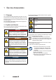
2 Sicherheit Dieser Abschnitt umfasst allgemeine Sicherheitshinweise zum Umgang mit dem Produkt. Spezifische Warnhinweise zu konkreten Handlungen und Situationen sind an den entsprechenden Stellen in der Dokumentation angeführt. Die Nichtbeachtung der Sicherheits- und Warnhinweise kann zu Verletzungen und Sachschäden führen. 2.1 Allgemeine Sicherheitshinweise –– Vor allen Arbeiten am Produkt muss das Produkt ausgeschaltet und frei von gefährlicher Spannung sein (siehe Abschnitt 2.2).
Sicherheit –– Achten Sie auf die richtige Polung und Zuordnung der Strangleitungen. –– Schließen Sie nur Strangleitungen mit identischen Leerlaufspannungen an. ►►Schalten Sie den Wechselrichter mit dem ausgangsseitigen Lasttrennschalter wieder ein. 2.3 Bestimmungsgemäßer Gebrauch Die PV Next String Combiner Box ist dafür vorgesehen, in die elektrische Gleichstromverbindung zwischen Photovoltaik-Modulen und Wechselrichter installiert zu werden. Jede andere Verwendung gilt als nicht bestimmungsgemäß.
3 Produktbeschreibung max. 3 Strings an 1 MPPT max. 6 Strings an 2 MPPT max. 3 Strings max. 9 Strings an 3 MPPT max. 6 Strings Bild 3.1 Übersicht der Produktvarianten an 1 MPPT(im Bild nur Modelle mit PV-Steckverbindern, ohne optionale an 2Schalter MPPT oder Kabelverschraubungen) 3.
Produktbeschreibung Best.-Nr. Typ Best.-Nr.
Produktbeschreibung 1 5 6 2 11 7 3 4 3 8 9 5 1 6 2 12 7 10 4 10 8 9 Bild 3.
Produktbeschreibung 1 2 1 6 2 3 6 3 7 4 4 8 4 4 8 5 5 5 1 1 2 2 6 7 4 8 5 6 3 3 4 5 4 4 8 5 5 5 Bild 3.3 Übersicht der Komponenten (Beispiele, rechts: Variante mit Sicherungseinsätzen) 1 2 3 4 5 6 7 8 10 Leiterplatte Betriebsmittelkennzeichnung Überspannungsschutz DC-Leiterplattenklemme für Strangeingang DC-Leiterplattenklemme für Ausgang zum Wechselrichter Fernmeldekontakt Überspannungsschutz Sicherungseinsätze Leiterplattenklemme für Funktionserdung 2690250000/03/09.
Produktbeschreibung 3.2 Gehäuse Die PV Next String Combiner Box ist mit Kabelverschraubungen (A) und optional mit PV-Steckverbindern (B) ausgestattet. PV-Steckverbinder verringern den Zeitaufwand bei Installation und Wartung. Die Steckverbinder erfüllen die Anforderungen der Norm DIN EN 50521. 3.5 Dichtungsset SL SET PV next Bild 3.
Produktbeschreibung 3.8 Sicherungshalter mit Sicherungseinsatz (optional) Äußeres Blitzschutzsystem vorhanden Trennungsabstand S ≥ 0.7 … 1.0 m eingehalten Kabellänge I2 < 10 m – – – – – x – – – – – x – x x – Typ II x x x x x – x x x x – – x – x x – – x – x Bild 3.9 Sicherungshalter mit Sicherungseinsatz Jeder Sicherungshalter ist mit einer Silberschicht überzogen und mit einer Feder ausgerüstet.
Produktbeschreibung 3.11 Technische Daten Allgemeine Daten Anschließbare MPPT 1 ... 6 Strangeingänge pro MPPT 2 ... 6 Ausgänge pro MPPT 1 ... 6 Zulässige Umgebungstemperatur Betrieb -20 ºC ... +50 ºC, siehe Typenschild Zulässige Umgebungstemperatur Lagerung und Transport -20 ºC ...
Produktbeschreibung Elektrische Daten Maximaler Eingangsspannung 1000 V DC Maximaler Strom pro Strangeingang (Inc) 10 ... 15 A DC, siehe Typenschild Maximaler Kurzzeitstrom pro Strangeingang 1,25 × Inc Maximaler Strom pro PV-Steckverbinder 35 A DC Maximaler Strom pro MPPT 30 ...
4 Transport und Lagerung 4.1 Transport 4.3 Lagerung ►►Beachten Sie das Gesamtgewicht und verwenden Sie geeignete Transportmittel. Bei längerer Lagerung müssen die zulässigen Umgebungsbedingungen eingehalten werden (siehe technische Daten). ACHTUNG 4.2 Lieferung auspacken ACHTUNG Mögliche Zerstörung des Produkts! Die Steckverbinder und die Kabelverschraubungen am Gehäuseboden können beschädigt werden. ►►Legen Sie das Produkt nach dem Auspacken immer auf der Rückseite ab.
5 Montage 5.1 Montageort Die PV Next String Combiner Box ist für die geschützte Außenaufstellung geeignet. Für den sicheren Betrieb und um Schäden am Produkt zu vermeiden, müssen bei der Auswahl des Montageorts die folgenden Anforderungen beachtet werden. –– Der Montageort darf nicht in einer Umgebung liegen, in der sich brennbare Flüssigkeiten, Gase oder Stäube befinden können.
Montage 5.2 Produkt montieren Achten Sie bei der Montage darauf, dass keine Feuchtigkeit, Staub oder Fremdkörper in das Produkt eindringen. ACHTUNG Sachschaden durch ungeeignete Schrauben! Ein zu kleiner oder zu großer Durchmesser von Schraube oder Schraubenkopf kann dazu führen, dass sich die Schraube in der Befestigungsbohrung verkeilt und das Gehäuse beschädigt. Aus demselben Grund sind Senkkopfschrauben ungeeignet.
Montage 5.
Montage W D H D H Y X Best.-Nr. Y 2737440000 2737480000 2737490000 2737500000 2737520000 2737530000 2737540000 2737550000 X Typ D W PVN1M1I6SXF3V1O1TXPX10 PVN1M1I6S0F3V1O1TXPX10 PVN1M1I6SXF3V2O1TXPX10 H PVN1M1I6S0F3V2O1TXPX10 PVN1M1I6SXF3V1O0TXPX10 PVN1M1I6S0F3V1O0TXPX10 PVN1M1I6SXF3V2O0TXPX10 PVN1M1I6S0F3V2O0TXPX10 X 2690250000/03/09.
6 Inbetriebnahme 6.1 Voraussetzungen für die Inbetriebnahme 6.2 PV Next String Combiner Box in Betrieb nehmen Die PV Next String Combiner Box ist vollständig montiert. ►►Prüfen Sie vor der Inbetriebnahme, ob das Produkt unbeschädigt ist. Falls das Gehäuse, die Leiterplatte oder einzelne Bauteile Beschädigungen oder starke Verschmutzungen aufweisen, nehmen Sie das Produkt nicht in Betrieb. Wenden Sie sich an Ihre Weidmüller Vertretung oder Ihren Vertriebshändler.
Inbetriebnahme Variante mit Kabelverschraubungen: ►►Entfernen Sie die Kappen und die Gummidichtungen der M25-Kabelverschraubungen für IN + und OUT + sowie IN – und OUT –. ►►Setzen Sie in jede Kabelverschraubung einen neuen Mehrfachdichteinsatz (3 x 7 mm) ein und montieren Sie die beiden Kappen. ►►Falls nicht alle Öffnungen des Mehrfachdichteinsatzes benötigt werden, verschließen Sie alle nicht benötigten Öffnungen mit den beiliegenden Blindstiften (Ø 7 x 28 mm).
7 Reinigung ACHTUNG Mögliche Zerstörung des Produkts! Das Gehäuse und der Deckel können durch Reinigungsmittel, Scheuermittel, Lösungsmittel und Hochdruckreiniger beschädigt werden. ►►Verwenden Sie zur Reinigung ein mit klarem Wasser befeuchtetes Tuch. ►►Reinigen Sie die PV Next String Combiner Box in regelmäßigen Abständen, so dass die Warnsymbole jederzeit gut sichtbar sind. ►►Reinigen Sie das Gehäuse nur äußerlich und in geschlossenem Zustand.
8 Wartung Die PV Next String Combiner Box ist wartungsarm. Die Anschlüsse aller DC-Leitungen sind als wartungsfreie, selbst-nachstellende PUSH IN-Federkraftklemmen ausgeführt. –– Einmal jährlich muss eine Sichtprüfung durchgeführt werden. –– Mindestens alle 5 Jahre muss eine intensivere Wartung und Kontrolle aller Komponenten durchgeführt werden. Achten Sie bei Wartungsarbeiten darauf, dass keine Feuchtigkeit, Staub oder Fremdkörper in das Produkt eindringen.
Wartung Für diese Arbeit benötigen Sie geeignetes Werkzeug: –– Sicherungswechselzange oder Kombizange –– Multimeter ►►Demontieren Sie den Deckel vom Gehäuse. ►►Ziehen Sie den Sicherungseinsatz mit dem Werkzeug senkrecht zur Leiterplatte aus dem Sicherungshalter heraus, ohne dabei den Sicherungshalter zu verbiegen. ►►Kontrollieren Sie den Sicherungshalter optisch auf Beschädigungen und den korrekten Sitz der Überfeder.
Wartung 8.7 Ersatzteile und Zubehör 3. 4. Bild 8.3 Überspannungsableiter einsetzen ►►Falls Sie keine weiteren Arbeiten durchführen wollen, verschließen Sie die PV Next String Combiner Box wieder. 8.5 Isolationswiderstand prüfen Die Messung des Isolationswiderstands bei gesteckten Überspannungsschutz-Ableitern führt zu einer Fehlmessung. ►►Entfernen Sie vor der Messung die Überspannungsschutz-Ableiter (siehe Kapitel 8.4).
9 Außerbetriebnahme und Entsorgung 9.1 Außerbetriebnahme GEFAHR Unmittelbare Lebensgefahr An spannungsführenden Teilen können bis zu 1.000 V DC anliegen. ►►Schalten sie die Anlage aus wie in Kapitel 2.2 beschrieben. ►►Beachten Sie die Dokumentation des Wechselrichterherstellers. 1. Demontieren Sie den Gehäusedeckel von der PV Next String Combiner Box. 2. Trennen Sie alle Verbindungen von der PV Next String Combiner Box. 3.
Contents 1 1.1 1.2 About this documentation Target group Symbols and notes 28 28 28 2 2.1 2.2 2.3 2.4 2.5 2.6 Safety General safety note Switching off and on safely Intended use Personnel Legal notice Warnings on the product 29 29 29 29 30 30 30 3 3.1 3.2 3.3 3.4 3.5 3.6 3.7 3.8 3.9 3.10 3.
1 About this documentation 1.1 Target group These operating instructions are intended for the operator of the photovoltaic system (PV system) and for all persons handling the product during its life cycle. The required knowledge of this group of persons is defined in the safety chapter. 1.2 Symbols and notes The warnings contained in the documentation are divided into hazard categories.
2 Safety This section includes general safety notes for handling the product. Specific warnings for specific tasks and situations are given at the appropriate places in the documentation. Failure to observe the safety notes and warnings can result in physical injury and property damage. 2.1 General safety note –– Before carrying out any work on the product, it must be switched off and free of dangerous voltage (see section 2.2). This reduces the risk of electric shocks or arcing.
Safety 2.
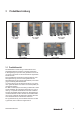
3 Product description max. 3 strings on 1 MPPT max. 6 strings on 2 MPPTs max. 3 strings on 1 MPPT max. 9 strings on 3 MPPTs max. 6 strings on 2 MPPTs Figure 3.1 Overview of the variants (only models with PV-connectors shown, without optional switches or cable glands) 3.1 Product overview The Weidmüller PV Next String Combiner Boxes are standardised string combiners with which photovoltaic string cables in private or commercial PV systems can be connected safely and easily to the inverters.
Product description Order No. Type Order No.
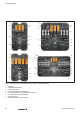
Product description 1 5 6 2 11 7 3 4 3 8 9 5 1 6 2 12 7 10 4 10 8 9 Figure 3.
Product description 1 2 1 6 2 3 6 3 7 4 4 8 4 4 8 5 5 5 1 1 2 2 6 7 4 8 5 6 3 3 4 5 4 4 8 5 5 5 Figure 3.3 Overview of the components (examples, right: variant with fuse links) 1 2 3 4 5 6 7 8 34 Printed circuit board (PCB) Equipment identifier Surge protection DC PCB terminal for string input DC PCB terminal for output to the inverter Remote signalling contact surge protection Fuse links PCB terminal for functional earth 2690250000/03/09.
Product description 3.2 Enclosure The PV Next String Combiner Box is equipped with cable glands (A) and optionally with PV connectors (B). PV connectors reduce installation and maintenance time. The connectors meet the requirements of the DIN EN 50521 standard. 3.5 SL SET PV next seal set The combiner box is supplied with one bag per PCB/ MPPT containing the SL SET PV next seal set (Order No. 2729230000). enthalten.
Product description 3.8 Fuse holder with fuse link (optional) Outer lightning protection system present Separation distance S ≥ 0.7 … 1.0 m fulfilled Cable length I2 < 10 m – – – – – x – – – – – x – x x – Type II x x x x x – x x x x – – x – x x – – x – x Figure 3.9 Fuse holder with fuse link Each fuse holder is covered with a silver layer and supplied with a spring. This ensures a long life contact between the fuse link and the fuse holder.
Product description 3.11 Technical data General data MPPT suitable for connection 1 ... 6 String inputs per MPPT 2 ... 6 Outputs per MPPT 1 ... 6 Permissible ambient temperature in operation -20ºC ... +50ºC, see type plate Permissible ambient temperature for storage and transport -20ºC ...
Product description Electrical data Maximum input voltage 1,000 V DC Maximum current per string input (Inc) 10 ... 15 A DC, see type plate Maximum short-time withstand current per string input 1.25 × Inc Maximum current per PV connector 35 A DC Maximum current per MPPT 30 ...
4 Transport and storage 4.1 Transport 4.3 Storage ►►Observe the total weight and use appropriate transportation equipment. For longer storage periods, the approved environmental conditions must be observed (see "Technical data"). ATTENTION 4.2 Unpacking the delivery ATTENTION The product can be destroyed! The connectors and the cable glands on the enclosure bottom can be damaged. ►►Always place the product on the rear side after unpacking.
5 Installation 5.1 Installation site The PV Next String Combiner Box is suitable for protected outdoor installation. For safe operation and to avoid damage to the product, the following requirements must be observed when selecting the installation site. –– The installation site must not be located in an environment where flammable liquids, gases or dusts may be present. Work on the PV Next String Combiner Box can produce sparks that can ignite a potentially explosive air mixture.
Installation 5.2 Mounting the product During installation, make sure that no moisture, dust or foreign objects can penetrate into the product. ATTENTION Damage to property due to unsuitable screws! If the diameter of the screw or screw head is too small or too large, the screw may become wedged in the mounting hole and damage the enclosure. For the same reason, countersunk screws are unsuitable. ►►For wall mounting, use screws with the properties described below.
Installation 5.
Installation W D H D H Y X Order No. Y 2737440000 2737480000 2737490000 2737500000 2737520000 2737530000 2737540000 2737550000 X Type D W PVN1M1I6SXF3V1O1TXPX10 PVN1M1I6S0F3V1O1TXPX10 PVN1M1I6SXF3V2O1TXPX10 H PVN1M1I6S0F3V2O1TXPX10 PVN1M1I6SXF3V1O0TXPX10 PVN1M1I6S0F3V1O0TXPX10 PVN1M1I6SXF3V2O0TXPX10 PVN1M1I6S0F3V2O0TXPX10 X 2690250000/03/09.
6 Commissioning 6.1 Preconditions for commissioning The PV Next String Combiner Box is fully mounted. ►►Before commissioning, check that the product is not damaged. If the enclosure, printed circuit board or individual components are damaged or heavily soiled, do not operate the product. Contact your Weidmüller representative or distributor. During commissioning, ensure that no moisture, dust or foreign objects can penetrate into the product.
Commissioning Variant with cable glands: ►►Remove the caps and the rubber seals from the M25 cable glands for IN + and OUT + as well as IN – and OUT –. ►►Insert the new multiple sealing insert (3 x 7 mm) into each cable gland and fit both caps. ►►If not all openings of the multiple sealing insert are required, seal all openings that are not required with the supplied blind pins (Ø 7 x 28 mm).
7 Cleaning ATTENTION The product can be destroyed! The enclosure and cover may be damaged by detergents, scouring agents, solvents and high-pressure cleaners. ►►Use a cloth moistened with clear water for cleaning. ►►Clean the PV Next String Combiner Box at regular intervals so that the warning symbols are always clearly visible. ►►Only clean the exterior of the enclosure when it is closed. ►►Take care not to damage the sticker with warning symbols. 46 2690250000/03/09.
8 Maintenace The PV Next String Combiner Box is low-maintenance. The connections of all DC cables are designed as maintenance-free, self-adjusting PUSH IN spring-loaded terminals. –– A visual inspection must be carried out once a year. –– More intensive maintenance and inspection of all components must be carried out at least every five years. During maintenance work, make sure that no moisture, dust or foreign objects can penetrate into the product.
Maintenace ►►Carefully push the (new) fuse link into the fuse holder using the tool. Take care not to damage the PCB! ►►Make sure that the fuse links are properly seated in the fuse holders by visually checking the position of the fuse link between the clamping jaws of the fuse holder. ►►If you do not want to carry out any further work, close the PV NextString Combiner Box again. 2. 1. 8.3 Checking surge protection arresters Weidmüller surge protection devices are equipped with replaceable arresters.
Maintenace 8.
9 Decommissioning and disposal 9.1 Decommissioning DANGER Imminent risk to life! Up to 1,000 V DC can be present on live parts. ►►Switch off the system as described in chapter 2.2. ►►Refer to the inverter manufacturer's documentation. 1. Remove the enclosure cover from the PV Next String Combiner Box. 2. Disconnect all connections from the PV Next String Combiner Box. 3. Loosen the screws on the wall mount and remove the product from the wall. 9.
ANHANG Elektroanschlussplan 52 APPENDIX Electrical connection layout 2690250000/02/02.
Rev. Brief description Date -XD11 1 -XD12 1 3 2 1 Edited by -XD13 OUT+ -XD1 1 1 -XD14 1 2 -XD15 1 3 /1.12 +UZ2/1.6 +UZ2/1.12 +UZ3/1.6 +UZ3/1.
Rev. Brief description Date 1 -XD12 1 Edited by -XD13 OUT+ -XD1 1 1 -XD14 1 2 -XD15 1 3 Name Date Name PV NEXT Project description 4 2+ 2+ 4 1 2 CABLE GLAND -XD5 -FA3 -FA2 -FA1 14 14 14 -XE1 -FA2 11 (COM) 11 12 11 12 11 12 +UZ1-XE1:2 OPTION +UZ1/1.9 / Schematic Diagram Page description +UZ2-XD10 / -XD11 3 2 1 +UZ1/1.6 +UZ1/1.12 /1.12 +UZ3/1.6 +UZ3/1.
Rev. Brief description Date 1 -XD12 1 Edited by -XD13 1 1 -XD14 1 2 -XD15 1 3 Name Date Name PV NEXT Project description 4 3+ 3+ 4 +UZ2/1.9 / 1 2 CABLE GLAND -XD5 -FA3 -FA2 -FA1 14 14 14 -XE1 -FA2 11 (COM) 11 12 11 12 11 12 +UZ2-XE1:2 OPTION Schematic Diagram Page description +UZ3-XD10 / -XD11 OUT+ -XD1 +UZ1/1.6 +UZ1/1.12 +UZ2/1.6 +UZ2/1.12 /1.