
User Documentation


92493040000/00/09.16
Instructions for safe use
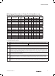
Tightening information (Point 15), cable sizes (mm),
construction and armour acceptance (mm)
Gland
size
Tighten Mid
Cap using
wrench up to
Max Ø
over
cores
Max
No of
Cores
Inner Sheath Outer Sheath Reduced Bore
Armour
size
Universal
Max Min Max Min Max
16 ½-turn 9.0 15 11.7 8.4 13.5 6.7 10.3 0.1 -1.25
20S ½-turn 10.4 35 11.7 11.5 16.0 9.4 12.5 0.1 -1.25
20 ½-turn 12.5 40 14.0 15.5 21.1 12.0 17.6 0.1 -1.25
25 ½-turn 17.8 60 20.0 20.3 27.4 16.8 23.9 0.1 -1.6
32 ½-turn 23.5 80 26.3 26.7 34.0 23.2 30.5 0.1 -2.0
40 ½-turn 28.8 130 32.2 33.0 40.6 28.6 36.2 0.1 -2.0
50S ½-turn 34.2 200 38.2 39.4 46.7 34.8 42.4 0.1 -2.5
50 ½-turn 39.4 400 44.1 45.7 53.2 41.1 48.5 0.1 -2.5
63S ½-turn 44.8 400 50.1 52.1 59.5 47.5 54.8 0.1 -2.5
63 ½-turn 50.0 425 56.0 58.4 65.8 53.8 61.2 0.1 -2.5
75S ½-turn 55.4 425 62.0 64.8 72.2 60.2 68.0 0.1 -2.5
75 ½-turn 60.8 425 68.0 71.1 78.0 66.5 73.4 0.1 -2.5
80 ¾-turn 64.4 425 72.0 77.0 84.0 71.9 79.4 0.1 -3.15
85 ¾-turn 69.8 425 78.0 79.6 90.0 75.0 85.4 0.1 -3.15
90 ¾-turn 75.1 425 84.0 88.0 96.0 82.0 91.4 0.1 - 3.15
100 ¾-turn 80.5 425 90.0 92.0 102.0 87.4 97.4 0.1 -3.15
Installation Guidance
Point Advice
1
• EN/IEC 60079-10 Classification of Hazardous Areas
• EN/IEC 60079-14 Electrical Installations in Hazardous Areas
• EN/IEC 60079-31 Ignitable dust – Protection by enclosure
• BS 6121, Part 5 Selection, Installation & Maintenance of Cable Glands
2 Installation should only be carried out by a competent electrician, skilled in cable gland installation.
3 NO INSTALLATION SHOULD BE CARRIED OUT UNDER LIVE CONDITIONS.
4
Threaded entries: the product can be installed directly into threaded entries. Threaded entries should comply with clause 5.3 of
IEC/EN 60079-1 and have a lead-in chamfer to allow for full engagement of the threads. For Ex d applications a minimum of 5 fully engaged
parallel threads is required. Metric threads are supplied with an o-ring and will maintain IP66 and IP68. Parallel entry threads will maintain an
IP rating of IP64. A sealing washer should be used to maintain all IP ratings greater than IP64.
5
To maintain the Ingress Protection rating of the product, the entry hole must be perpendicular to the surface of the enclosure. The surface
should be sufficiently flat and rigid to make the IP joint. The surface must be clean and dry. It is the users/installers responsibility to ensure
that the interface between the enclosure and cable gland is suitably sealed for the required application.
6
Whilst Weidmuller products with tapered threads, when installed into a threaded entry, have been tested to maintain IP66 without
any additional sealant, due to the differing gauging tolerances associated with the use of tapered threads it is recommended to use a
non-hardening thread sealant if an IP rating higher than IP64 is required.
7
Once installed do not dismantle except for routine inspection. An inspection should be conducted as per IEC/EN 60079-17. After inspection
the gland should be re-assembled as detailed in points 15 and 16, ensuring the Mid Cap and back nut are correctly tightened to ensure the
installation is secure.