
User Documentation


72493040000/00/09.16
Instructions for safe use
STEP-BY-STEP FITTING INSTRUCTION
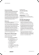
1. Split gland as shown. Warning. The entry body of this
cable gland is coated with a releasing agent to ensure
the compound form can be inspected after curing. The
entry body should not be treated with any lubricant or
be exposed to any solvents. The internal bore of the
entry body must not be damaged. Any handling during
the course of normal installation will not effect the
operation of the releasing agent.
2. Fit Entry Body. Hand-tighten, then suitably secure with
a wrench.
3. Slide Back Nut, Mid Cap and Clamp onto cable as
shown
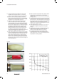
4. CABLE PREPARATION Strip off outer jacket, length
to suit installation
For armoured cable:
A Cut armour. For approximate exposed lengths see
Table 1 column 4
B Where sheath sizes are near minimum, form armour
to facilitate clamping (arrow A)
For all cables:
C Remove inner sheath, length to suit installation. Lead
sheath must be cut to push through the continuity
washer. Remove protective foils, and any cords/
fillers from around and between the cores. Take care
not to cut the insulating sleeves of the cores. Pigtail
and sleeve screens to be passed through compound
5. Slide Cone onto inner sheath and under armour.
For lead sheath push through the continuity washer
ensuring contact is made. Slide Clamp onto exposed
armour.
6. Insert cable through Entry Body and engage Cone in
Entry Body
7. To clamp armour onto Cone, hand-tighten Mid Cap to
Entry Body, then using wrench tighten a further 1 turn.
Cable with maximum diameter wire armour may require
an additional ½ to 1 turn
8. Unscrew Mid Cap to visually check armour is securely
clamped. Pull out cable and Cone. If armour has not
clamped repeat the clamping process.
HEALTH AND SAFETY WARNING
The resin used in the compound can cause eye
and skin irritation. For your personal protection,
wear the gloves supplied while mixing and
applying. The uncured compound should not be
allowed to come into contact with foodstuffs.
A COMPREHENSIVE SAFETY DATA
SHEET PROVIDED BY THE COMPOUND
MANUFACTURER IS AVAILABLE ON REQUEST
COMPOUND EXTRUSION
COMPLETED
INSTALLATION
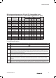
TABLE 1
Gland
Size
16 – 25
32 – 40
50S – 75
80 – 100
20 – 22 mm
30 mm
32 mm
50 mm
40 mm
45 mm
50 mm
60 mm
Armour
Length
Compound
Length
41
1
SPLIT GLAND
Entry Body Cone Clamp
Continuity washer (Where fitted)
Mid Cap Back Nut
STEP-BY-STEP FITTING INSTRUCTIONS
CABLE
PREPARATION
COMPOUND
PACKING
Lead Sheath
Lead Sheath