
User Documentation


72493050000/00/09.16
Instructions for safe use
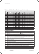
Table 1 - Cable Sizes and Armour Acceptance (mm)
Cable Sizes (mm), Armour Acceptance (mm) & Assembly Data NOTE: *Only 9.3 mm diameter on silicone seal options
Gland
size
Mid Cap Turns
– Step 10
Back Nut Turns
– Step 11
Inner Sheath Outer Sheath Reduced Bore Armour Acceptance Ranges
Min Max Min Max Min Max Wire Tape/Woven Wire/Braid
16 1 1 3.5 8.4 8.4 13.5 4.9 10.3 0.9 0.15 – 0.35
20S 1 1 8.0 11.7 11.5 16.0 9.4 12.5 0.9 – 1.25 0.15 – 0.35
20 1 1 6.7* 14.0 15.5 21.1 12.0 17.6 0.9 – 1.25 0.15 – 0.50
25 1 1 13.0 20.0 20.3 27.4 16.8 23.9 1.25 – 1.6 0.15 – 0.50
32 1 2 19.0 26.3 26.7 34.0 23.2 30.5 1.6 – 2.0 0.15 – 0.55
40 1 1 25.0 32.2 33.0 40.6 28.6 36.2 1.6 – 2.0 0.2 – 0.6
50S 1 1 31.5 38.2 39.4 46.7 34.8 42.4 2.0 – 2.5 0.2 – 0.6
50H 1 2 31.5 38.2 39.4 46.7 34.8 42.4 2.0 – 2.5 0.2 – 0.6
50 1 2 36.5 4 4.1 45.7 53.2 41.1 48.5 2.0 – 2.5 0.5 – 0.8
63S 1 1 42.5 50.1 52.1 59.5 47.5 54.8 2.5 0.5 – 0.8
63H 1 1 42.5 50.1 52.1 59.5 47.5 54.8 2.5 0.5 – 0.8
63 1 1 49.5 56.0 58.4 65.8 53.8 61.2 2.5 0.5 – 0.8
75S 1
3
⁄4 1 54.5 62.0 64.8 72.2 60.2 68.0 2.5 0.5 – 1.0
75H 1
3
⁄4 1 54.5 62.0 71.1 78.0 66.5 73.4 2.5 0.5 – 1.0
75 1
3
⁄4 1 60.5 68.0 71.1 78.0 66.5 73.4 2.5 0.5 – 1.0
80 1
1
⁄4 1 62.2 72.0 77.0 84.0 71.9 79.4 3.15 0.5 – 1.0
80H 1
1
⁄4 1 62.2 72.0 79.6 90.0 75.0 85.4 3.15 0.5 – 1.0
85 1
1
⁄4 1 69.0 78.0 79.6 90.0 75.0 85.4 3.15 0.5 – 1.0
90 1 3 74.0 84.0 88.0 96.0 82.0 91.4 3.15 0.5 – 1.0
90H 1 1 74.0 84.0 92.0 102.0 87.4 97.4 3.15 0.5 – 1.0
100 1 1 82.0 90.0 92.0 102.0 87.4 97.4 3.15 0.5 – 1.0
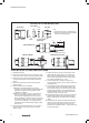
Installation Guidance
Point Advice
1
• EN/IEC 60079-10 Classification of Hazardous Areas
• EN/IEC 60079-14 Electrical Installations in Hazardous Areas
• EN/IEC 60079-31 Ignitable dust – Protection by enclosure
• BS 6121, Part 5 Selection, Installation & Maintenance of Cable Glands
2 Installation should only be carried out by a competent electrician, skilled in cable gland installation.
3 NO INSTALLATION SHOULD BE CARRIED OUT UNDER LIVE CONDITIONS.
4
Threaded entries: the product can be installed directly into threaded entries. Threaded entries should comply with clause 5.3 of
IEC/EN 60079-1 and have a lead-in chamfer to allow for full engagement of the threads. For Ex d applications a minimum of 5 fully engaged
parallel threads is required. Parallel entry threads will maintain an IP rating of IP64. A sealing washer should be used to maintain all IP ratings
greater than IP64.
5
Clearance holes: these may be 0.1 to 0.7mm larger than the major diameter of the male thread. The product should be secured with a lock
nut and the threads tightened to ensure the cable gland is secure. A sealing washer should be used to maintain IP ratings. A serrated washer
should be used for additional installation protection.
6
To maintain the Ingress Protection rating of the product, the entry hole must be perpendicular to the surface of the enclosure. The surface
should be sufficiently flat and rigid to make the IP joint. The surface must be clean and dry. It is the users/installers responsibility to ensure
that the interface between the enclosure and cable gland is suitably sealed for the required application.
7
Whilst Weidmuller products with tapered threads, when installed into a threaded entry, have been tested to maintain IP66 without any
additional sealant, due to the differing gauging tolerances associated with the use of tapered threads it is recommended to use a non-
hardening thread sealant if an IP rating higher than IP64 is required.
8
Once installed do not dismantle except for routine inspection. An inspection should be conducted as per IEC/EN 60079-17. After inspection
the gland should be re-assembled as instructed, ensuring the mid cap and back nut are correctly tightened to ensure the cable is secure.
9
For Ex d applications, these glands should only be used with substantially round and compact cables with extruded bedding (i.e. effectively
filled cables) that are compliant with EN/IEC 60079-14.
10 If used in a non-metallic increased safety enclosure, the gland must be included within in the earth circuit of the system.