
User Documentation


Instructions for safe use
2493050000/00/09.166
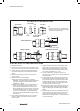
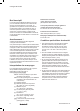
STEP-BY-STEP FITTING INSTRUCTIONS
1. Split gland as shown.
2. Remove the Inner Seal. This must be removed to effec-
tively clamp armour. Remove Continuity Washer if fitted.
3. Fit Entry Body to enclosure including sealing washer
if required. Hand-tighten, then suitably secure with a
wrench.
4. Slide Rear Assembly (and shroud if required) onto
cable as shown.
5. Prepare cable as shown in diagram.
A Strip the outer sheath and armour to suit the
installation. For lead sheathed cable the lead sheath
must pass through the Continuity Washer when
installation is complete.
B Expose armour approx. 20 mm long and slide the
Clamp over the exposed armour. Slide cone on
to inner sheath and spread armour over the cone.
Where sheath sizes are near minimum, form armour
to facilitate clamping as shown. Ensure the Clamp
is in the correct orientation. The clamp should be
positioned so that the identification ring(s) are away
from the cone.
6. Insert cable through Entry Body. Do not re-fit seal or
continuity washer. Push cable forward to maintain
armour contact.
7. Support the cable to prevent it from twisting. Hand
tighten Mid Cap to Entry Body to lock onto armour.
When tight, further tighten Mid Cap 1 full turn with
wrench. Cable with maximum diameter wire armour
may require an additional ½ to 1 turn.
8. Loosen off Mid Cap to visually check armour is
securely locked. If armour has not clamped repeat the
clamping process.
9. Pull out cable from Entry Body. Re-fit the inner seal
(and continuity washer on lead sheath options). Re-
insert cable through the seal, (and continuity washer
if fitted) and Entry Body. For lead sheath cable the
Continuity Washer must be in contact with the lead
sheath & must be in front of the seal.
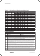
10. Re-tighten Mid Cap to the entry body. Ensure the seal
makes full contact with cable inner sheath and then
tighten the Mid Cap by the additional turns detailed in
Table 1.
11. Hold Mid Cap with wrench and tighten Back Nut onto
cable. Ensure the seal makes full contact with cable
outer sheath and then tighten the back nut by the
additional turns detailed in Table 1. If fitted, pull shroud
over gland assembly.
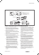
Rear Assembly
SPLIT GLAND
Example of
formed armour
AB
CABLE PREPARATION
ARMOUR CLAMPING COMPLETED INSTALLATION
Entry Body Inner
Seal
Cone
Continuity Washer
(Where fitted)
Clamp
Mid Cap Back Nut
Note.
1. Clamp for wire armour has 1 identification ring
2. Clamp for woven steel wire, braid and steel tape
armours has 2 identification rings
STEP-BY-STEP FITTING INSTRUCTIONS