
User Documentation


INSTRUCTIONS FOR SAFE USE
Issue: 5 Weidmüller Interface GmbH & Co. KG
Date: 29/04/2013 Klingenbergstrasse 16, 32758 Detmold, Germany
Doc: WA108 Page: 2 of 2
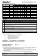
Table 1 - Cable Sizes and Armour Acceptance (mm)
Cable Sizes (mm), Armour Acceptance (mm) & Assembly Data NOTE:- *Only 9.3 mm diameter on silicone seal options
Inner Sheath Outer Sheath Reduced Bore Armour Acceptance Ranges Gland
Size
Mid Cap Turns
– Step 10
Back Nut Turns
– Step 11
Min Max Min Max Min Max Wire Tape/ Woven Wire/Braid
16 1
1
3.5 8.4 8.4 13.5 4.9 10.3 0.9 0.15 – 0.35
20S 1
1
8.0 11.7 11.5 16.0 9.4 12.5 0.9 – 1.25 0.15 – 0.35
20 1
1
6.7* 14.0 15.5 21.1 12.0 17.6 0.9 – 1.25 0.15 – 0.50
25 1
1
13.0 20.0 20.3 27.4 16.8 23.9 1.25 – 1.6 0.15 – 0.50
32 1
2
19.0 26.3 26.7 34.0 23.2 30.5 1.6 – 2.0 0.15 – 0.55
40 1
1
25.0 32.2 33.0 40.6 28.6 36.2 1.6 – 2.0 0.2 – 0.6
50S 1
1
31.5 38.2 39.4 46.7 34.8 42.4 2.0 – 2.5 0.2 – 0.6
50H 1
2
31.5 38.2 39.4 46.7 34.8 42.4 2.0 – 2.5 0.2 – 0.6
50 1
2
36.5 44.1 45.7 53.2 41.1 48.5 2.0 – 2.5 0.5 – 0.8
63S 1
1
42.5 50.1 52.1 59.5 47.5 54.8 2.5 0.5 – 0.8
63H 1
1
42.5 50.1 52.1 59.5 47.5 54.8 2.5 0.5 – 0.8
63 1
1
49.5 56.0 58.4 65.8 53.8 61.2 2.5 0.5 – 0.8
75S 1 ¾
1
54.5 62.0 64.8 72.2 60.2 68.0 2.5 0.5 – 1.0
75H 1 ¾
1
54.5 62.0 71.1 78.0 66.5 73.4 2.5 0.5 – 1.0
75 1 ¾
1
60.5 68.0 71.1 78.0 66.5 73.4 2.5 0.5 – 1.0
80 1 ¼
1
62.2 72.0 77.0 84.0 71.9 79.4 3.15 0.5 – 1.0
80H 1 ¼
1
62.2 72.0 79.6 90.0 75.0 85.4 3.15 0.5 – 1.0
85 1 ¼
1
69.0 78.0 79.6 90.0 75.0 85.4 3.15 0.5 – 1.0
90 1
3
74.0 84.0 88.0 96.0 82.0 91.4 3.15 0.5 – 1.0
90H 1
1
74.0 84.0 92.0 102.0 87.4 97.4 3.15 0.5 – 1.0
100 1
1
82.0 90.0 92.0 102.0 87.4 97.4 3.15 0.5 – 1.0
Installation Guidance
Point Advice
1
♦ EN/IEC 60079-10 Classification of Hazardous Areas
♦ EN/IEC 60079-14 Electrical Installations in Hazardous Areas
♦ EN/IEC 60079-31 Ignitable dust – Protection by enclosure
♦ BS 6121, Part 5 Selection, Installation & Maintenance of Cable Glands
2 Installation should only be carried out by a competent electrician, skilled in cable gland installation.
3 NO INSTALLATION SHOULD BE CARRIED OUT UNDER LIVE CONDITIONS.
4 Threaded entries: the product can be installed directly into threaded entries. Threaded entries should comply with clause 5.3 of IEC/EN 60079-1
and have a lead-in chamfer to allow for full engagement of the threads. For Ex d applications a minimum of 5 fully engaged parallel threads is
required. Parallel entry threads will maintain an IP rating of IP64. A sealing washer should be used to maintain all IP ratings greater than IP64.
5 Clearance holes: these may be 0.1 to 0.7mm larger than the major diameter of the male thread. The product should be secured with a lock nut and
the threads tightened to ensure the cable gland is secure. A sealing washer should be used to maintain IP ratings. A serrated washer should be
used for additional installation protection.
6 To maintain the Ingress Protection rating of the product, the entry hole must be perpendicular to the surface of the enclosure. The surface should
be sufficiently flat and rigid to make the IP joint. The surface must be clean and dry. It is the users/installers responsibility to ensure that the
interface between the enclosure and cable gland is suitably sealed for the required application.
7 Whilst Weidmuller products with tapered threads, when installed into a threaded entry, have been tested to maintain IP66 without any additional
sealant, due to the differing gauging tolerances associated with the use of tapered threads it is recommended to use a non-hardening thread sealant
if an IP rating higher than IP64 is required.
8 Once installed do not dismantle except for routine inspection. An inspection should be conducted as per IEC/EN 60079-17. After inspection the
gland should be re-assembled as instructed, ensuring the mid cap and back nut are correctly tightened to ensure the cable is secure.
9 For Ex d applications, these glands should only be used with substantially round and compact cables with extruded bedding (i.e. effectively filled
cables) that are compliant with EN/IEC 60079-14.
10 If used in a non-metallic increased safety enclosure, the gland must be included within in the earth circuit of the system.
Interpretation of Markings. Markings on the outside of this gland carry the following meanings:
KDSW [a] [b] [c] [d] [e] [f] [ggg] or alternatively KDSX [a] [b] [c] [d] [e] [f] [ggg]
Where: [a] = Entry thread
[b] = Main component material (B = brass, S = stainless steel)
[c] = Seal material (S = silicone, N = Neoprene)
[d] = Continuity for lead sheath (L = yes, O = no)
[e] = Plating (Sc = self coloured, Ni = Nickel, Zi = zinc)
[f] = Reduced bore outer seal (1 = yes, 2 = no)
[ggg] = Gland size (Gsss) (e.g. G20S)
Certificate Numbers (ATEX) SIRA 05ATEX1286X (IECEx) IECEx SIR 05.0067X
Protection Concept, EPL’s and Gas Groups: Ex d IIC Gb / Exe IIC Gb / Ex ta IIIC Da
Environmental Protection: IP66 / IP68 (50 metres for 7 Days)
ATEX (EU Directive 94/9/EC) Markings: II 1D II 2G
Special Conditions for Safe Use
1. These glands must not be used with enclosures where the temperature at the point of mounting exceeds -35°C to +90°C using
neoprene seals, or –60° to +180°C using silicone seals.
2. These glands, when installed in accordance with the manufacturers instructions and with an appropriate enclosure on which they are fixed,
are capable of providing an ingress protection of IP66 and IP68 (50 metres 7 days)
3. If these cable glands only grip the cable sheath of the cable and do not clamp the cable armour or if they are used to terminate
unarmoured, braided or screened cables, then they shall only be used for fixed installations, hence the cables shall be effectively clamped
to prevent pulling or twisting.
4. Where glands without sealing rings are installed in protection by enclosure (Ex t) equipment for use in explosive dust atmospheres, they
shall only be fitted into enclosures offering a minimum of 5 full threads, in accordance with EN 60079-31:2009 clause 5.1.1.