
User Documentation


INSTRUCTIONS FOR SAFE USE
Issue: 5 Weidmüller Interface GmbH & Co. KG
Date: 29/04/2013 Klingenbergstrasse 16, 32758 Detmold, Germany
Doc: WA108 Page: 1 of 2
Klippon
KlipponKlippon
Klippon
®
KDSW & KDSX Cable Glands
The KDSW & KDSX type cable gland is for outdoor use in the appropriate Hazardous Areas with armoured cable. It gives environmental protection to
IP66 and IP68. A termination suitable for EMC protection can be made using armoured cables with these glands. KDSW type clamp steel wire armour
and KDSX types clamp woven steel wire and steel tape armours.
Warning
PLEASE STUDY CAREFULLY BOTH PAGES OF THESE INSTRUCTIONS BEFORE INSTALLATION. These glands should not be used in any
application other than those mentioned here or in our Data Sheets, unless Weidmuller states in writing that the product is suitable for such application.
Weidmuller can take no responsibility for any damage, injury or other consequential loss caused where the glands are not installed or used according to
these instructions. This leaflet is not intended to offer advice on the selection of cable glands. Further guidance can be found in the standards listed
overleaf.
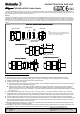
Example of
formed armour
AB
STEP-BY-STEP FITTING INSTRUCTIONS
1 Split gland as shown.
2 Remove the Inner Seal. This must be removed to effectively clamp armour. Remove Continuity Washer if fitted.
3 Fit Entry Body to enclosure including sealing washer if required. Hand-tighten, then suitably secure with a wrench.
4 Slide Rear Assembly (and shroud if required) onto cable as shown.
5 Prepare cable as shown in diagram.
A Strip the outer sheath and armour to suit the installation. For lead sheathed cable the lead sheath must pass through the
Continuity Washer when installation is complete.
B Expose armour approx. 20mm long and slide the Clamp over the exposed armour. Slide cone on to inner sheath and
spread armour over the cone. Where sheath sizes are near minimum, form armour to facilitate clamping as shown.
Ensure the Clamp is in the correct orientation. The clamp should be positioned so that the identification ring(s) are away
from the cone.
6 Insert cable through Entry Body. Do not re-fit seal or continuity washer. Push cable forward to maintain armour contact.
7 Support the cable to prevent it from twisting. Hand tighten Mid Cap to Entry Body to lock onto armour. When tight, further
tighten Mid Cap 1 full turn with wrench. Cable with maximum diameter wire armour may require an additional ½ to 1 turn.
8 Loosen off Mid Cap to visually check armour is securely locked. If armour has not clamped repeat the clamping process.
9 Pull out cable from Entry Body. Re-fit the inner seal (and continuity washer on lead sheath options). Re-insert cable through
the seal, (and continuity washer if fitted) and Entry Body. For lead sheath cable the Continuity Washer must be in contact
with the lead sheath & must be in front of the seal.
10 Re-tighten Mid Cap to the entry body. Ensure the seal makes full contact with cable inner sheath and then tighten the Mid
Cap by the additional turns detailed in Table 1
11 Hold Mid Cap with wrench and tighten Back Nut onto cable. Ensure the seal makes full contact with cable outer sheath and
then tighten the back nut by the additional turns detailed in Table 1. If fitted, pull shroud over gland assembly.
0344
STEP
STEPSTEP
STEP-
--
-BY
BYBY
BY-
--
-STEP FITTING INSTRUCTIONS
STEP FITTING INSTRUCTIONSSTEP FITTING INSTRUCTIONS
STEP FITTING INSTRUCTIONS
CABLE PREPARATION
CABLE PREPARATIONCABLE PREPARATION
CABLE PREPARATION
ARMOUR CLAMPING
ARMOUR CLAMPINGARMOUR CLAMPING
ARMOUR CLAMPING
COMPLETED INSTALLATION
COMPLETED INSTALLATIONCOMPLETED INSTALLATION
COMPLETED INSTALLATION
Rear Assembly
SPLIT GLAND
Entry Body
Inner
Seal
Cone
Continuity Washer
(Where fitted)
Clamp
Mid Cap Back Nut
Note.
1. Clamp for wire armour has 1 identification ring
2. Clamp for woven steel wire, braid and steel tape
armours has 2 identification rings