Wireless Access Point / Bridge / Client IE-WL-AP-BR-CL-ABG-EU IE-WL-AP-BR-CL-ABG-US IE-WLT-AP-BR-CL-ABG-EU IE-WLT-AP-BR-CL-ABG-US Hardware Installation Guide Second Edition, August 2016 1243450000/01/08.16 Please note: This document, the detailed manual and any further product information - if available - can be downloaded from the website: http://www.weidmueller.
Overview Weidmüller’s Wireless Access Point/Client/Bridge is ideal for applications that are hard to wire, too expensive to wire, or use mobile equipment that connects over a TCP/IP network. The WLAN device is rated to operate at temperatures ranging from 0 to 60°C for standard models and -40 to 75°C for extended temperature models and is rugged enough for any harsh industrial environment. Installation is easy, with either DIN-Rail mounting or distribution boxes.
ATTENTION For security reasons, we strongly recommend changing the password. To do so, select Maintenance Password, and then follow the on-screen instructions. Step 5: Select the operation mode for the IE-WL-AP-BR-CL-ABG By default, the IE-WL-AP-BR-CL-ABG’s operation mode is set to AP. You can change the setting in Wireless Settings Basic Wireless Settings if you would like to use Client mode.
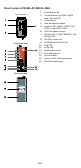
Panel Layout of IE-WL-AP-BR-CL-ABG Top Panel View 1. 2. 3. 4. 5. 6. 7. Front Panel View 8. 9. 10. 11. 12. 13. 14. 15. 16.
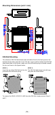
Mounting Dimensions (unit = mm) DIN-Rail Mounting The aluminum DIN-Rail attachment plate should be fixed to the back panel of the wireless device when you take it out of the box. If you need to reattach the DIN-Rail attachment plate to the device, make sure the stiff metal spring is situated towards the top, as shown in the figures below. STEP 1: STEP 2: Insert the top of the DIN-Rail into the slot The DIN-Rail attachment unit will snap just below the stiff metal spring. into place as shown below.
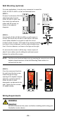
Wall Mounting (optional) For some applications, it may be more convenient to mount the IE-WL-AP-BR-CL-ABG to a wall, as illustrated below. STEP 1: Remove the aluminum DIN-Rail attachment plate from the IE-WL-AP-BR-CL-ABG, and then attach the wall mount plates with M3 screws, as shown in the adjacent diagrams. STEP 2: Mounting the IE-WL-AP-BR-CL-ABG to a wall requires 4 screws. Use the IE-WL-AP-BR-CL-ABG device, with wall mount plates attached, as a guide to mark the correct locations of the 4 screws.
WARNING Safety First! Calculate the maximum possible current in each power wire and common wire. Observe all electrical codes dictating the maximum current allowed for each wire size. If the current goes above the maximum ratings, the wiring could overheat, causing serious damage to your equipment. You should also pay attention to the following items: • • • • Use separate paths to route wiring for power and devices.
Wiring the Redundant Power Inputs The top two pairs of contacts of the 10-contact terminal block connector on the IE-WL-AP-BR-CL-ABG’s top panel are used for the IE-WL-AP-BR-CL-ABG’s two DC inputs. Top and front views of the terminal block connector are shown below. STEP 1: Insert the negative/positive DC wires into the V-/V+ terminals. STEP 2: To keep the DC wires from pulling loose, use a small flat-blade screwdriver to tighten the wire-clamp screws on the front of the terminal block connector.
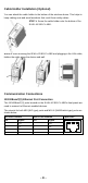
Cable Holder Installation (Optional) You can attach the cable holder to the bottom of the wireless device. This helps to keep cabling neat and avoid accidents that result from untidy cables. STEP 1: Screw the cable holder onto the bottom of the IE-WL-AP-BR-CL-ABG. STEP 2: After mounting the IE-WL-AP-BR-CL-ABG and plugging in the LAN cable, tighten the cable along the device and wall.
RS-232 Connection The IE-WL-AP-BR-CL-ABG has one RS-232 (8-pin RJ45) console port located on the front panel. Use either an RJ45-to-DB9 or RJ45-to-DB25 cable to connect the console port of the wireless device to your PC’s COM port. You may then use a console terminal program to access the IE-WL-AP-BR-CL-ABG for console configuration. Console Pinouts for 10-pin or 8-pin RJ45 10-Pin Description 1 ----2 DSR 3 RTS 4 GND 5 TxD 6 RxD 7 DCD 8 CTS 9 DTR 10 ----- NOTE 1. 2.
LED Indicators The front panel of Weidmüller’s IE-WL-AP-BR-CL-ABG contains several LED indicators. The function of each LED is described in the table below. LED Color State Description Front Panel LED Indicators (System) On Power is being supplied from power input 1. PWR1 Green Power is not being supplied from power Off input 1. On Power is being supplied from power input 2. PWR2 Green Power is not being supplied from power Off input 2. On Power is being supplied via PoE.
Specifications WLAN Standards Spread Spectrum and Modulation Operating Channels (Central Frequency) Security Transmission Rates IEEE 802.11a/b/g for Wireless LAN IEEE 802.3u 10/100BaseT(X) for Ethernet LAN IEEE 802.3af for Power-over-Ethernet IEEE 802.1D/w STP/RSTP DSSS with DBPSK, DQPSK, CCK OFDM with BPSK, QPSK, 16QAM, 64QAM US: 2.412 to 2.462 GHz (11 channels) 5.18 to 5.24 GHz (4 channels) EU: 2.412 to 2.472 GHz (13 channels) 5.18 to 5.
Power Input Voltage Input Current Reverse Polarity Protection Mechanical Casing Dimensions Weight Installation Environmental Operating Temperature 12 to 48 VDC, redundant dual DC power inputs or 48 VDC Power-over-Ethernet (IEEE 802.3af) 0.494A-0.121A (@ 12-48VDC) 0.3A @24 VDC Present IP30 protection, aluminum case 53.6 x 135 x 105 mm (2.11 x 5.31 x 4.13 in) 850g DIN-Rail, or wall mounting Standard models: 0 to 60°C (32 to 140°F) Wide Temp.
ATTENTION Use the antennas correctly: The 2.4 GHz antennas are needed when the IE-WL-AP-BR-CL-ABG operates in IEEE 802.11b/g. The 5 GHz antennas are needed for IEEE802.11a. Make sure your antenna installation is within a safety area, which is covered by a lightning protection or surge arrest system. Contact Information Weidmüller Interface GmbH & Co. KG Postfach 3030 32760 Detmold Klingenbergstraße 16 32758 Detmold Germany Phone +49 (0) 5231 14-0 Fax +49 (0) 5231 14-2083 E-Mail info@weidmueller.