Gigabit Ethernet Switch – Basic Line IE-SW-BL05-4GT-1GS IE-SW-BL05T-4GT-1GS Hardware Installation Guide First Edition, May 2016 2467470000/00/05.16 Important note: This document and additional product information can be downloaded using following link: http://www.weidmueller.
Overview The BasicLine Gigabit Ethernet Switches are equipped with 5 Gigabit Ethernet ports (4x 10/100/1000BaseT(X) ports and 1x combo 10/100/1000BaseT(X) or 100/1000BaseSFP port), making them ideal, economical solutions for demanding, high bandwidth Gigabit Ethernet applications.
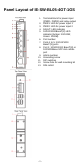
Panel Layout of IE-SW-BL05-4GT-1GS 1. 2. 3. 4. 5. 6. 7. 8. 9. 10. 11. 12. 13.
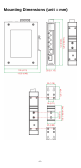
Mounting Dimensions (unit = mm) -4-
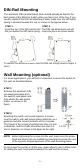
DIN-Rail Mounting The aluminum DIN-rail attachment plate should already be fixed to the back panel of the Ethernet Switch when you take it out of the box. If you need to reattach the DIN-rail attachment plate, make sure the stiff metal spring is situated towards the top, as shown in the figures below. STEP 1: STEP 2: Insert the top of the DIN-rail into the The DIN-rail attachment unit will slot just below the stiff metal spring. snap into place as shown below.
STEP 3: Once the screws are fixed in the wall, insert the four screw heads through the large parts of the keyhole-shaped apertures, and then slide the switch downwards, as indicated. Tighten the four screws for added stability. ATEX Information 1. Certificate number: ATEX: DEMKO 16 ATEX 1727X 2. Ambient range: -40°C ≤ Tamb ≤ +75°C for models with suffix of “-T”; -10°C ≤ Tamb ≤ +60°C for models without suffix of “-T” 3. Certification string: ATEX: Ex II 3G Ex nA nC IIC T4 Gc 4.
WARNING Safety First! Calculate the maximum possible current in each power wire and common wire. Observe all electrical codes dictating the maximum current allowable for each wire size. If the current goes above the maximum ratings, the wiring could overheat, causing serious damage to your equipment. You should also pay attention to the following items: Use separate paths to route wiring for power and devices.
FAULT: The two middle contacts of the 6-contact terminal block connector are used to detect both power faults and port faults. The two wires attached to the Fault contacts form an open circuit when: 1. Ethernet Switch has lost power from one of the DC power inputs. OR 2. The PORT ALARM DIP switch for one of the ports is set to ON, but the port is not connected properly. If neither of these two conditions is satisfied, the Fault circuit will be closed.
Communication Connections IE-SW-BL05(T)-4GT-1GS switches have 2 types of communication port: • • 4 x 10/100/1000BaseT(X) Ethernet ports 1 x Combo-port, usable as 10/100/1000T(X) or 100/1000BaseSFP port 10/100/1000BaseT(X) Ethernet Port Connection The 10/100/1000BaseT(X) ports located on switch’s front panel are used to connect to Ethernet-enabled devices.
RJ45 (8-pin) to RJ45 (8-pin) Straight-Through Cable Wiring RJ45 (8-pin) to RJ45 (8-pin) Cross-Over Cable Wiring 100/1000BaseSFP (mini-GBIC) Fiber Port One of the Gigabit Ethernet ports on the IE-SW-BL05(T)-4GT-1GS is a SFP slot, which requires 100M or 1G mini-GBIC fiber transceivers to work properly. Weidmüller offers several SFP-transceiver models for various distance requirements. The concept behind the LC port and cable is straightforward. Suppose you are connecting devices I and II.
ATTENTION This is a Class 1 Laser/LED product. To avoid causing serious damage to your eyes, do not stare directly into the laser beam. Redundant Power Inputs Both power inputs can be connected simultaneously to live DC power sources. If one power source fails, the other live source acts as a backup, and automatically supplies all of the switch´s power needs. Alarm Contact The Ethernet switch has one Alarm Contact located on the top panel.
DIP Switch Setting ON OFF ON OFF BSP Jumbo Frame ON 802.3az OFF 100/1000BaseSFP ON OFF ON Port Alarm OFF Description Enables broadcast storm protection Disables broadcast storm protection Enables jumbo frame function Disables jumbo frame function Enables the energy-efficient Ethernet function Disables the energy-efficient Ethernet function Supports 100M SFP module Supports 1000M SFP module Enables the corresponding PORT Alarm.
Auto MDI/MDI-X Connection The Auto MDI/MDI-X function allows users to connect the Ethernet Switch 10/100/1000BaseT(X) ports to any kind of Ethernet device, without paying attention to the type of Ethernet cable being used for the connection. This means that you can use either a straight-through cable or cross-over cable to connect the Ethernet Switch to Ethernet devices.
Specifications Technology Standards Interface RJ45 Ports Fiber Ports LED Indicators DIP Switch Alarm Contact IEEE 802.3 for 10BaseT IEEE 802.3u for 100BaseT(X) and 100BaseFX IEEE 802.3ab for 1000BaseT(X) IEEE 802.3z for 1000BaseX IEEE 802.3x for Flow Control IEEE 802.
MTBF (meantime between failures) Time 2,823,446 hrs Database Telcordia (Bellcore), GB 25°C Warranty Time Period 5 years Weidmüller gives a 5 year warranty on this product in accordance with the warranty terms as described in the general conditions of sale of the Weidmüller company which has sold the products to you.