Installation Guide 7 SERIES Professional TurboChef Speedcook Double Oven VDOT730
Table of Contents Warnings and Important Information _______________________________ 3 Dimensions _____________________________________________________ 6 Specifications ___________________________________________________ 7 Cutout Dimensions ______________________________________________ 8 General Information ______________________________________________ 9 Installation _____________________________________________________ 10 Performance Checklist ___________________________________________ 14 Control Panel
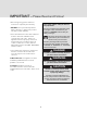
IMPORTANT – Please Read and Follow! • Before beginning, please read these instructions completely and carefully. Your safety and the safety of others is very important. • DO NOT remove permanently affixed labels, warnings, or plates from product. This may void the warranty. We have provided many important safety messages in this manual and on your appliance. ALWAYS read and obey all safety messages. • All local and national codes and ordinances must be observed.
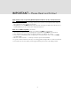
IMPORTANT – Please Read and Follow! A GFI shall be used if required by NFPA-70 (National Electric Code), federal/state/local laws, or local ordinances. • The required use of a GFI is normally related to the location of a receptacle with respect to any significant sources of water or moisture. • Viking Range, LLC will NOT warranty any problems resulting from GFI outlets which are not installed properly or do not meet the requirements below.
IMPORTANT – Please Read and Follow! WARNING DANGER To prevent possible damage to cabinets and cabinet finishes, use only materials and finishes that will not discolor or delaminate and will withstand temperatures up to 194°F (90°C). Heat resistant adhesive must be used if the product is to be installed in laminated cabinetry. Check with your builder or cabinet supplier to make sure that the materials meet these requirements.
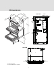
Dimensions 28 (71-1/ .4 8” cm ) * 4” m) 2 c .0 (61 ” /8 ) m 3-7 c 8 (9. 30 (76-1/1 .5 6” cm ) ” /8 ) m 3-1 9c (7. SIDE VIEW 7/16" (0.44 cm) 4”cm) .2 (10 (10 4” .2 cm UPP ER OFF ) 5 (120–3/ 8.0 8” cm ) LOW OFFER 5 (120–7/ 9.2 8” cm ) 2” -1/ ) 20.1 cm (52 TOP VIEW 24"* (61.0 cm) 1" (2.5 cm) 1" (2.
Specifications TurboChef Double Oven Description VDOT730 Product width outside cabinet 30-1/16" (76.5 cm) Product height outside cabinet 50-7/8" (129.2 cm) Product depth outside cabinet cabinet to front of display/doors — 3-1/8" (7.9 cm) with bottom door open — 20-1/2" (52.1 cm) Cutout height 50-5/8" (128.6 cm) Cutout depth 24" (61.0 cm) Cutout width 28-1/2" (72.4 cm) Electrical requirements 4-wire ground, 240-208VAC, 50 amp electrical connection Unit equipped with No.
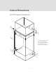
Cutout Dimensions VDOT730 TurboChef Double Oven Ju nc tio LoBox n ca tio n 1” (2. Min 5c . m) (10 4” .2 cm ) 5” 28 50 (72-1/2 .6 ” cm ) (12 -5/8 8.6 ” cm ) (12 Min .7 . cm ) ” 24 cm) (61 .0 To obtain proper fit of the oven into the cabinets, the junction box must be located either above or below the oven opening. 11 ” (28 Mi .2 n. cm ) lls waular e r su dic ke en Maperp are Ju nc tio LoBox n ca tio n 8 5” (12 Min .7 . cm ) 4 (10 ” .
General Information Recommendations for Moving • All openings in the wall behind the appliance or in the floor under the appliance should be sealed. • The appliance is heavy – use extreme care when handling! • Keep appliance area clear and free from combustible materials, gasoline and other flammable vapors. • WARNING: DO NOT use the handle or oven door to lift the oven. Remove lower door before installation to ensure that it is not used to lift the unit. DO NOT remove the upper door.
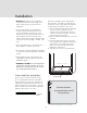
Installation • BE SURE that support for this appliance is perpendicular to the front facing of the wall or cabinet before you perform the installation. Attach the skid plate before installing the two slide rails. If possible, the rails should be placed on top of any studs that might be located under the cabinet interior floor. 1. Remove adhesive backing from skid plate. Center across the inside front of the cabinet opening with flange and screw locations on front outer edge.
Installation Headline (cont.) 3 2 Open lower oven door completely. Fold latches backward until locked in place LOW ER OFF 5 4 Lift door up and out. Slowly close until latches stop door. 7 6 Remove racks. Unscrew pallet screws from side of oven.
Installation Headline (cont.) 8a WARNING ELECTRICAL FIRE HAZARD White Improper connection of aluminum house wiring to copper leads can result in an electrical hazard or fire. Use only connectors designed for joining copper to aluminum and follow the manufacturer's recommended procedure closely.
Installation Headline (cont.) UPPE OFF R 11 12 Remove center grille by removing screws underneath grille. Push grille up and pull out. LOW OFFER Attach screws thru the framing from front of unit on both sides in the center and bottom. There are no mounting holes at the top LOW OFFER 13 14 Replace center grille by pushing in and down. Replace screws underneath grille. Replace racks. Reattach door to oven. LOW OFFER 15 16 Close door. Open door completely.
Performance Headline Checklist – Lower Oven Loading the Software This first time you turn on the oven after installation, the oven will load the software. This process should take no longer than 10 minutes. DO NOT attempt to operate the oven while the software is loading. Note: If necessary to relaunch the software, hold down the left (upper) power off button for 5 seconds.
Service & Registration Headline If service is required, call your authorized service agency. Have the following information readily available. • Model number • Serial number • Date purchased • Name of dealer from whom purchased Clearly describe the problem that you are having.
Viking Range, LLC 111 Front Street Greenwood, Mississippi 38930 USA (662) 455-1200 For product information, call 1-888-(845-4641) or visit our web site at vikingrange.com in the US or brigade.