SERVICE NOTEBOOK VCWB300 PROFESSONAL MODEL BUILT-IN FULL HEIGHT WINE COOLER
Table of Contents Technical Information--------------------------------------------------------------------- 4 Sealed System------------------------------------------------------------------------------ 5 Control Panel Assembly------------------------------------------------------------------- 6 Mode of Operation------------------------------------------------------------------------ 6 Temperature Readout and Setting----------------------------------------------- 7 Display Off-------------------------------
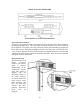
VCWB300 DDWB300 DESIGNER – DFWB300 FULL OVERLAY BUILT-IN FULL HEIGHT WINE COOLER VIKING TECHNICAL INFORMATION * DUE TO POSSIBLITY OF PERSONAL INJURY OR PROPERTY DAMAGE, ALWAYS CONTACT AN AUTHORIZED TECHNICIAN FOR SERVICING OR REPAIR OF THIS WINE COOLER. The Viking Built-in Full Height 30” W. wine cooler (VCWB series) is designed to meet the needs of the upscale wine connoisseur while also meeting Viking Range Corporation’s stringent product standards. The product is 30” (76.2cm) wide and 84” (213.
SEALED SYSTEM The sealed system consists of the following components (listed in order of refrigerant flow): 1 condenser coil 1 dryer assembly 3 solenoid valves 3 heat exchangers 3 evaporators 1 compressor 1 discharge tube 1 drain pan heater 1 pre-condenser loop Refrigerant Type – HFC 134a Refrigerant Charge – 7.3 oz.
CONTROL PANEL ASSEMBLY The wine cooler is equipped with a control panel conveniently located in the top front of the top compartment of the wine cooler. From this point the user can operate all functions of the wine cooler’s temperature management and various electronic features. The control panel housing is constructed of injected molded plastic. A glass keyboard is fastened to the housing by means of snap clips that are incorporated into the molded housing.
and appropriate zone valve based upon the temperature at the evaporator thermistor and will turn off the zone valve based upon the temperature at the chamber thermistor. Temperature readout and setting: Pressing the zone button will change which chamber is selected for adjustments. The selected chamber will have a bar displayed over the temperature reading on the VFD. Pressing the higher or lower buttons will raise or lower the set point of the selected chamber in one degree F increments.
Showroom mode: This mode, selected by closing the showroom switch is intended to simulate normal operation in all ways except the cooling and temperature alarm functions. Closure of this switch will over-ride normal cooling. Temperature displayed for the chambers will be the last temperatures stored in memory, or the factory defaults setting if they have not been changed. Lights and functions will occur as in normal cooling operation described above.
GLASS MULLION SHELF Each compartment is separated be a fixed glass shelf (“Mullion” – two per wine cooler). These glass shelves are uniquely designed such that they act not only as an insulated divider wall, but also provides a means of draining the condensate water from the top and middle compartments and as a means of attaching and supporting the light tubes for the middle compartment. The bottom trim of the shelf has holes for mounting the assembly to the cabinet of the wine cooler.
DISPLAY PANEL KEYBOARD ELECTRONIC FUNCTION DESCRIPTION Power Disconnect Switch: The power on/off switch is used to turn the power off to the wine cooler when cleaning it or changing the light tubes. The wine cooler is shipped with the power on/off switch in the on position. To turn the power off, remove the center grille assembly by grasping the three center louvers, lifting up and pulling outward. Press the power on/off switch to the “ON” position.
DISPLAY PANEL OPERATION Keyboard Entry Tone Zone Pad Indicates a pad was pressed, command read and accept. 1. Toggle between zones for set point temperature adjustment. Pressing immediately toggles from Top to mid to bottom, respectively that order. Entry tone will sound at each depression of pad. 2. Used in conjunction with “Higher Temp” and “Lights” pads to enter service mode. Press “Zone”, “Higher Temp” and “Lights” simultaneously for 5 seconds to activate service mode. 3.
Display Pad 1. Activates control panel. Pressing button for 2 seconds toggles the display on/off. Entry tone will sound at after 2 seconds of pad depression. 2. Activates Holiday Mode. Pressing button for 15 seconds toggles the holiday mode on/off. 3. Used in conjunction with “alarm” pad to toggle between “F” Fahrenheit and “C” Celsius temperature reading. Press and hold “Alarm” and “Display simultaneously for 10 seconds to change from one to the other (“F” or “C”) 4.
LEVELING ADJUSTMENTS DOOR STOP ADJUSTMENT 1. 2. Using a 3/16” allen wrench, remove door stop pin located in bottom hinge. The pin is factory set 110°. For 120° swing, move the pin to the utmost forward stop hole. For 90° swing, move the pin to the utmost rear stop hole. HINGE ADJUSTMENT 1. 2. 3. Using 3/16” allen wrench, remove the door stop pin located in bottom hinge.
DIAGNOSTIC CHECK POINTS (Rfer to Wiring Schematic on Page 19) Number DescriptionA E1 1 2 3 Display Board Send +5Vdc data signals ground 1 2 3 4 5 6 7 8 9 10 11 12 Touch switch inputs (with switches connected), typical +5VDC Ground Common for measurements on E2 Not connected When button is touched +4Vdc to +5Vdc, otherwise less than +1Vdc. When button is touched +4Vdc to +5Vdc, otherwise less than +1Vdc. When button is touched +4Vdc to +5Vdc, otherwise less than +1Vdc.
DIAGNOSTIC CHECK POINTS (con’t) E4 Thermister inputs (measured with thermisters disconnected). 1 to 8 3 to 4.5 VDC – TE2 (Evaporator Thermister #2) 2 to 9 3 to 4.5 VDC – TC1 (Compartment Thermister #1) 3 to 10 3 to 4.5 VDC – TE1 (Evaporator Thermister #1) 4 to 11 3 to 4.5 VDC – TC3 (Compartment Thermister #3) 5 to 12 3 to 4.5 VDC – TE3 (Evaporator Thermister #3) 6 to 13 3 to 4.5 VDC – TC2 (Compartment Thermister #2) 7 to 14 3 to 4.
General Information: Approved Board Certification Suction Discharge Process CSA – UL 0.256” + 0.005” / - 0.003” 0.194” + 0.003” / - 0.003” 0.256” + 0.005” / - 0.003” Mechanical Data: Low Starting Torque (LST) Lubricant Charge Lubricant type Lubricant Viscosity @ 40° C Weight (with Oil Charge) Nitrogen Charge 6.76 fl. Oz. ESTER ISO 22 15.43 lbs. 2.84 to 4.27 psig. Application: Evaporating Temperature range Refrigerant Refrigerant Charge Expanding Device Compressor Cooling LBP 32° C Ambient Temp.
THERMISTER RESISTANCE READING Using a Cup of Water (full of ice) at 32°F , place the Thermister in the water and you should read approximately 7353 Ω’s. DEG. F 25 26 27 28 29 30 31 32 33 34 35 36 37 38 39 40 41 42 43 44 45 46 47 48 49 50 51 52 53 54 55 56 57 58 59 60 61 62 DEG.
Solenoid Valve / Evaporator Fan FEATURES: Direct acting solenoid valve, designed to shut off refrigerating media. MOUNTING: Vertical with coil upwards preferred. During welding the central part of the body must not exceed 100° C. VALVE: Medium temperature from 10° C to + 90° C. Opening time 20 ms – closing time 20ms. COIL: Voltage tolerance +10% --15%. Compartment and Evaporator Thermister Location.
VCWB300 WIRING SCHEMATIC 19
VCWB300 WIRING DIAGRAM 20
TROUBLESHOOTING GUIDE PROBLEM A. Warm temperature in all Wine storage compartments. POSSIBLE CAUSE CORRECTION 1. Control set too warm Check set-points. Adjust setpoints colder. 2. Unit in Showroom Mode Adjust set-points and listen for compressor and condenser fan operation. If they do not energize, switch unit OFF then press and hold upper compartment colder & warmer keys while pressing unit On/OFF key. 3. Unit Recently Energized Allow 24 hours for unit to pull down. 4. Unit Recently Stocked 5.
TROUBLESHOOTING GUIDE (con’t) PROBLEM POSSIBLE CAUSE A. Warm temperature In all Wine Storage Compartments. CORRECTION b2 Check for continuity across the motor windings of the inoperative fan motor (See pages 14 and 19). 8. Condenser Air / Flow Condenser Fan Fault a. Dirty condenser b. Condenser fan blade loose or obstructed. c. Fan motor disconnected or malfunctioning. a. Clean condenser b. Check fan blade. Tighten or remove obstruction. c. Check fan motor operation. and electrical connections.
TROUBLESHOOTING GUIDE (con’t) PROBLEM POSSIBLE CAUSE CORRECTION 5. Door Ajar a. (See page 21) 6. Evaporator Thermistor Fault. a. (See page 17) 7. Condenser Air / Condenser Fan Fault. a. (See page 22) 8. Check Thermistors a. (See E4 checks, page 15) 9. Refrigerant Valve Solenoid Fault a. Solenoid disconnected or malfunctioning. 10. Sealed System leak or Restriction a. (See solenoid checks page 14) a. (See compressor data page 16) C.
TROUBLESHOOTING GUIDE (con’t) PROBLEM POSSIBLE CAUSE 2. Refrigerant Valve Solenoid Fault, Stuck Open 3. Room Temperature Below Set-Point CORRECTION a. Initiate manual valve activation mode on opposite valve as that suspected. Toggle to evaporator temp readings associated with suspected valve to verify it is closed. If it is open, check solenoid electrical connections to make sure they are not crossed. Unplug solenoid to see if valve closes. If valve closes, replace solenoid.
TROUBLESHOOTING GUIDE (con’t) PROBLEM POSSIBLE CAUSE 4. No Power from Control Board I. Control Panel Keys Inoperative or Malfunctioning 4. Check E15 to ground (See page 14). 1. Control Panel Ribbon Cable Plugged in Wrong 2. J. LED’s Do Not Illuminate. CORRECTION 1. 2. 3. 1. Check control panel ribbon cable (silver area on the ribbon cable terminal should be facing away from the control board). Plug in correctly if Incorrect. Control Panel or Ribbon 2. Check E2 test points page 14.