
Installation Instructions


MODELS G6MD • G8MD • G10MD
Page 7
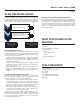
WIRE THE SYSTEM
BLACK (LINE)
WHITE (COMMON)
GREEN (GROUND)
MAKE-UP AIR DAMPER
TRANSFORMER
24V
PRESSURE
SWITCH
WIRING DIAGRAM
ONE DAMPER
24V
BLACK (LINE)
WHITE (COMMON)
GREEN (GROUND)
MAKE-UP AIR DAMPER
TRANSFORMER
24V
PRESSURE
SWITCH
WIRING DIAGRAM
MULTIPLE DAMPERS
MAKE-UP AIR DAMPER
24V 24V24V
TEST THE SYSTEM
Turn off the hood and check to see if the damper closes.
A qualified HVAC contractor should also ensure the proper operation and venting of all combustion equipment in the home.
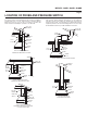
Wire the system as shown.
FALSE TRIPPING
Under certain extreme conditions there could be false tripping of the damper (opening when the range hood blower is off). If false tripping
is encountered, place an in-line backdraft damper (not included) between the probe and the roof or wall cap.
24V
20V
24V CONTACTS
TRANSFORMER WIRING