Form No. 3426-924 Rev C Debris Blower 600 Model No. 44536—Serial No. 403063082 and Up Register at www.Toro.com.
This product complies with all relevant European directives; for details, please see the separate product specific Declaration of Conformity (DOC) sheet. g000502 Figure 1 Safety-alert symbol WARNING CALIFORNIA Proposition 65 Warning Use of this product may cause exposure to chemicals known to the State of California to cause cancer, birth defects, or other reproductive harm. This manual uses 2 words to highlight information.
Safety • Do not put your hands or feet near moving General Safety • Do not operate the machine without all guards components of the machine. and other safety protective devices in place and working on the machine. This product is capable of throwing objects. Always follow all safety instructions to avoid serious personal injury. • Keep children, bystanders, and pets out of the operating area. Never allow children to operate the machine.
decal105-0627 105-0627 1. Warning—stop the engine, remove the ignition key before leaving the machine and disconnect the power take–off (PTO) shaft. decal105-0708 105-0708 1. Warning—thrown object hazard; keep bystanders away from machine. decal105-0628 105-0628 1. Warning—do not operate the machine with power take-off (PTO) at a greater angle than 15 degrees. decal105-0709 105-0709 1. Entanglement hazard, belt—keep all guards and shields in place; stay away from moving parts.
Setup Loose Parts Use the chart below to verify that all parts have been shipped. Procedure Description 1 2 3 4 5 6 7 8 9 10 Use Qty. CE entanglement decal 1 Apply the entanglement decal—CE mowers No parts required – Install the caster wheels. No parts required – Connect the lower link arms. No parts required – Connect the upper link. No parts required – Adjust the PTO shaft length. No parts required – Connect the PTO shaft. No parts required – Adjust the sway links.
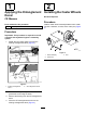
1 2 Applying the Entanglement Decal Installing the Caster Wheels No Parts Required CE Mowers Procedure Parts needed for this procedure: 1 Install a caster wheel assembly between each caster fork with 4 washers, an axle, and 2 cotter pins (Figure 3). CE entanglement decal Procedure Important: This procedure is required for all CE countries and anywhere English is commonly spoken. 1. Rotate the PTO shaft guard to access the existing entanglement decal (Figure 2). g011990 Figure 3 1.
3 4 Connecting the Lower Link Arms Connecting the Upper Link No Parts Required No Parts Required Procedure 1. Procedure 1. Position the blower on a flat, level surface and disengage the PTO. 2. Back the tractor squarely up to the blower until the lower link arms are aligned with the hitch pins. 3. Engage the parking brake, shut off the traction unit engine, and remove the key from the ignition.
5 Adjusting the PTO Shaft Length No Parts Required g011993 Figure 6 Procedure 1. PTO shaft 2. 37 mm (1-1/2 inches) dimension Important: A long PTO shaft is supplied with the machine to accommodate large variations in the tractor’s PTO and 3-point locations. For most machines, this shaft is too long and must be cut to the correct length, or damage may result. 5. Important: Incorrect PTO shaft length can cause A. machine and/or attachment damage and personal injury. 1. 2. B.
6 7 Connecting the PTO Shaft Adjusting the Sway Links No Parts Required No Parts Required Procedure Procedure 1. Connect the PTO shaft to the blower-input shaft. 2. Connect the PTO shaft to the rear tractor PTO shaft. 3. Slide the PTO shaft fully forward. 4. Depress the pin to secure the PTO shaft in place and slide the PTO shaft back and forth to ensure that it is properly locked. 5.
8 9 Adjusting the 3-Point-Lift Stop Removing the Blower from the Tractor No Parts Required No Parts Required Procedure Procedure Adjust and set the 3-point-lift stop to provide approximately 10 cm (4 inches) ground clearance, when in the raised position, to minimize the PTO angle when raising the blower. For transporting or trailer loading/unloading, the full-lift range can be used as long as the PTO tubes do not slide apart (Figure 9). 1.
Product Overview Operation Specifications Note: Determine the left and right sides of the machine from the normal operating position. Note: Specifications and design are subject to change without notice. Length 125 cm (49 inches) Width 150 cm (59 inches) Height 117 cm (46 inches) Net weight 227 kg (500 lbs) Before Operation Before Operation Safety General Safety • Never allow children or untrained people to Attachments/Accessories operate or service the machine.
Adjusting the Discharge Direction During Operation During Operation Safety The direction of the discharge opening can be changed from the side to the front by moving the control handle (Figure 10). General Safety • The owner/operator can prevent and is responsible for accidents that may cause personal injury or property damage. • Wear appropriate clothing, including eye protection; long pants; substantial, slip-resistant footwear; and hearing protection. Tie back long hair and do not wear loose jewelry.
• Reduce speed when operating on rough, uneven caves in. Establish a safety area between the machine and any hazard. terrain, and near curbs, holes, and other sudden changes in terrain. • To avoid causing the machine to tip over, be Operating Tips careful when turning and avoid unsafe maneuvers. • For all PTO shaft steel parts (tubes, bearings, WARNING joints, etc.) disassembly or repairs, it is highly advisable to contact your local Toro distributor.
After Operation After Operation Safety General Safety • Park the machine on a firm, level surface; shut off the traction unit engine, remove the key, wait for all moving parts to stop, and allow the machine to cool before adjusting, repairing, cleaning, or storing the machine. • Only disconnect the machine from the traction unit while on a level surface. • When disconnecting the machine, always chock the wheels to prevent movement.
Maintenance CAUTION Failure to properly maintain the machine could result in premature failure of machine systems causing possible harm to you or bystanders. Keep the machine well maintained and in good working order as indicated in these instructions. • Ensure that all guards are installed securely after Note: Determine the left and right sides of the machine from the normal operating position. maintaining or adjusting the machine.
Lubrication Drive Shaft Service Interval: Every 100 hours Greasing the Machine Grease the 2 drive-shaft fittings (Figure 13). The machine has grease fittings that you must lubricate regularly with No. 2 lithium grease. Fan-Shaft Bearings Service Interval: Every 100 hours Grease the 2 fan shaft bearings (Figure 11). Note: Remove belt cover to access rear fitting. g012000 Figure 13 g011998 Figure 11 Caster Wheels Service Interval: Every 100 hours Grease the 2 caster wheel fittings (Figure 12).
Belt Maintenance Adjusting the Blower Belt Service Interval: Every 20 hours Ensure that the belt is properly tensioned to ensure proper operation of the machine and unnecessary wear. Check the belt frequently. Important: The fasteners on the covers of this machine are designed to remain on the cover after removal. Loosen all of the fasteners on each cover a few turns so that the cover is loose but still attached, then go back and loosen them until the cover comes free.
Storage 1. Thoroughly clean the blower. Note: The fan housing should be free of dirt, leaves, and debris. 2. Lubricate all grease fittings. Wipe off any excess lubricant. 3. Place a light coat of grease on the splines of the PTO shaft. 4. Tighten all fasteners.
Troubleshooting Problem There is excessive vibration. Possible Cause 1. The bearing(s) on the fan shaft is damaged. 1. Replace the bearings. 2. Material is built up on the fan blades. 2. Clean out any build up on the inside of the housing. 3. Reduce the PTO speed to 540 rpm. 3. The engine speed of the PTO shaft is too fast. There is lack of adequate air flow. Corrective Action 1. The air slots are clogged with debris. 1. Clean out any debris from the slots. 2.
Notes:
EEA/UK Privacy Notice Toro’s Use of Your Personal Information The Toro Company (“Toro”) respects your privacy. When you purchase our products, we may collect certain personal information about you, either directly from you or through your local Toro company or dealer.
California Proposition 65 Warning Information What is this warning? You may see a product for sale that has a warning label like the following: WARNING: Cancer and Reproductive Harm—www.p65Warnings.ca.gov. What is Prop 65? Prop 65 applies to any company operating in California, selling products in California, or manufacturing products that may be sold in or brought into California.
The Toro Warranty Two-Year or 1,500 Hours Limited Warranty Conditions and Products Covered The Toro Company and its affiliate, Toro Warranty Company, pursuant to an agreement between them, jointly warrant your Toro Commercial product (“Product”) to be free from defects in materials or workmanship for 2 years or 1,500 operational hours*, whichever occurs first. This warranty is applicable to all products with the exception of Aerators (refer to separate warranty statements for these products).