
User's Manual

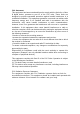
Table Of Contents
- Controls and Functions
- H Series
- Connect to the computer
- Picture in Picture(PIP) (L Series Only)
- Video instruction
- 1) Demonstrate the video usage of the device with common software AMCAP.
- DC IN 12V Power supply interface M/L Series
- DC IN 12V Power supply interface
- 3) Enable or disable the internal microphone
- 4) Remote upgrade mode
- 2) If the frame rate is not enough, the user can check whether the “ Use Frame
- Functions of the buttons on the top
- Pairing Wireless Microphones
- Installation instruction
- How is working in meeting rooms ?
- How is working in meeting rooms ?
- Buttons
- Notes-Tips
- Auto-Framing(H Series Only)

menu
4
Camera functions’
Camera zoom in
3
Zoom in
❶
2
6
Power on/off
Battery Working time
Video Conference Camera with Expansion Microphone(s)
Controls and Functions
< Front View >
Functions LEDs indicator
The indicator lights up when using the device.
H Series M Series L Series
Select “ AI Function” to “ON”,
Auto-Framing function turns on.
AI “Refresh Freq” is adjustable
“Low/Mid/High”.
Connect to the computer
❶ Connect the 12V power supply to the camera.
Connect the standard USB cable with the camera and computer or other host
computer. Refer to the following picture:
Lens
( 4K/2K optional )
C
amera Scroll wheel
Adjust ±15 degrees of the lens
2) The audio output of this device use the same USB interface with video and
supports the standard UAC protocol. All the software which supports the UAC
protocol can collect the audio of this device.
3) Daisy-chain max up to 3 wireless expansion microphones connect to main unit
via RF2.4G transmission. Each expansion microphone provides 3 meters pick up
range. To ensure the call quality and echo cancellation effect, please do not move
Picture in Picture(PIP) (L Series Only)
L Series support Picture in Picture(PIP) function, while EPTZ zooms in close-up,
users can view the panorama through the small picture-in-picture window.
DC 12V power supply
LAN(H Series only)
USB 3.0/2.0 cable
< Rear View >
H Series
go up and down. the expansion microphone after placing it on the table. At the same time,
expansion microphones need a distance at least 1 meter from the speaker.
4) The main unit has an internal auxiliary microphone for emergency use when
the expansion mics are out of power. Expansion mics are recommended for the
best call experience. When any expansion mic is turned on, the internal mic will
be automatically disabled.
Press “Camera functions
menu”(center), select “Image”
Video instruction
This device output video through USB. And it supports standard UVC protocol. All
the software which support the UVC protocol can collect the video of this device.
1) Demonstrate the video usage of the device with common software AMCAP.
❶
Open the AMCAP (available in
t
he CD) and click the Devices.
DC IN 12V Power supply interface
M/L Series
For LAN
For connecting USB3.0 Cable
Combination Key Function
2) Prompt tone ON/OFF
Prompt tone is turned on by default. Press and hold for 5 seconds to
Then choose the 4K UCamera
(or the similar option)
❷ Click the Options and
choose Preview. Then the
user can preview the video.
Refer to
the right picture.
4K UCamera
麦克风(17-USB Audio Device)
DC IN 12V Power supply interface
< Top View >
For connecting USB2.0 Cable
turn ON/OFF.
3) Enable or disable the internal microphone
Press and hold for 5 seconds to enable or disable the internal mic
4) Remote upgrade mode
Select “PIP” to “On” , Picture in
Picture function turns on, users
can see small picture-in-picture
window at the bottom of right.
2) If the frame rate is not enough, the user can check whether the “ Use Frame
Rate” is ticked off. If yes, please cancel the tick
Click the Capture and then
choose Set Frame Rate
Functions of the buttons on the top
1 Connection indicator
2 Microphone mute 3 Speakerphone
m
m
u
u
t
t
e
e
(This function needs the support of the manufacturer, please do not use it
under normal circumstances)
Press and hold for 5 seconds to enter remote upgrade mode, only the
orange indicator of Power button lights.
Press and hold for 5 seconds to exit the upgrade mode.
Pairing Wireless Microphones
microphone close to the main unit.
paired.
In Choose Frame Rate, check
whether the “Use Frame Rate”
is ticked off. If yes, please
cancel the tick. And then click
the Apply
Cancel the tick in the frame
4 Volume down 5 Volume up 6 Power on/off
Music Mode
main unit
Installation instruction
1 Desktop installation
Put the device on the table or
screen and make sure the
horizontal installation.
3) Change the different resolution and frame.
Click the Options and choose
Video Capture Pin...,
❷
< Wireless Expansion Microphones.Top View(left), bottom View(right) >
What is content in package ?
2 Bracket installation
Screw the bracket to the screw hole at the bottom of the device and tighten it.
Then the user can install a bracket at the bottom of the device. The screws of
the bracket must meet the following specifications.
Set the different resolution
and frame according the
user’s requirement. And
then click Apply
Click Apply
How is working in meeting rooms ?
1 Mute Microphone
2 Power on/off
3 Copper ring
①Video conference camera * 1
②User’s manual * 1
③Expansion mics * 1-3
④Charging tray * 1-2
⑤Bracket and screws * 1
⑥ USB 3.0 cable 3M (H Series) * 1
USB 2.0 cable 5M (M/L Series) * 1
⑦Power supply of the camera * 1
⑧Power supply of the charging tray * 1-2
⑨USB - type C cable * 1-2
⑩Remote control (no battery) * 1
Note:
φ=3mm
L=6mm
Screw specification
1 microphone 2 microphones
Remote control’s functions
①The bracket must be installed on the flat surface.
②The screws on the bracket of the video conference camera can’t be used
2
1
3
4
Buttons
1
Power on/off
on the higher place, just like the ceiling mount or partition mount.
3 Wall mount
❶Install the bracket at the bottom of the camera according to
6 5
the
Bracket installation .
Red LED flashes Low battery
Notes-Tips
1) High-end, mid-end and low-end configuration optional, support standard UVC
protocol.
7
Note: If the remote control is not available, maybe the batteries ran out. Please
change the new batteries(AAA*2pcs) .
Auto-Framing(H Series Only)
H Series support Auto-Framing camera control, automatically moves the lens and
adjusts the zoom to comfortably frame meeting participants in rooms of all
shapes and sizes.
Press “Camera functions menu”
(center), select “ Setup”
❷Screw the bracket on the wall, refer to the following picture 1.
❸Fasten the camera with bottom bracket on the wall mount, refer to the
following picture 2.
(Picture 1) (Picture 2)
Note:
③The wall mounted bracket must be flat
④The wall bracket is used in conjunction with the bracket. The device must
install the bracket
Speakerphone mute
Microphone mute
Camera zoom out
1
Mute Microphone
Volume down 4
Volume down
1 Connection indicator
Standby time
Charging time
“+” volume up; “-” volume down
7
Volume up/down
6
Speakerphone mute
5
Microphone mute
Camera functions’ menu (center)
EPTZ control (up, down, left, right)
2
Zoom out
Power on/off
Functions
When using the charging tray, the charging
copper ring acts as the charging interface.Charging
copper ring contacts spring probe for charging
3
Copper ring
Press 3 seconds to power on/off
2
Power on/off
Microphone mute
Functions
Buttons
Press 3 seconds to power off Blue LED off
Press 3 seconds to power on
Blue LED lights
Volume up
Blue LEDs increase
progressively
5
Volume up
Blue LEDs decrease
progressively
Speakerphone mute
Orange LED lights
3
Speakerphone mute
All the mics mute
Orange LED lights
2
Microphone mute
Disconnected Blue LED flashes
Connected to PC successfully via USB
Orange LED lights
Functions
Indicator status
Buttons
3 microphones
Horizontal placement
❷
❶
❷
❶
❷
❶