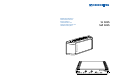
BEDIENUNGSANLEITUNG INSTRUCTIONS FOR USE NOTICE D‘EMPLOI ISTRUZIONI PER L‘USO INSTRUCCIONES PARA EL USO GEBRUIKSAANWIJZING SI 1015 SZI 1015 1
BEDIENUNGSANLEITUNG SI 1015 SZI 1015 BEDIENUNGSANLEITUNG .................................................................................................................................. 3 INSTRUCTIONS FOR USE .................................................................................................................................. 11 NOTICE D‘EMPLOI ..............................................................................................................................................
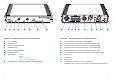
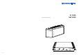
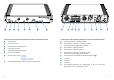
Anschluß- und Bedienelemente SI 1015 (Frontseite) Anschluß- und Bedienelemente SI 1015 (Rückseite) Ein- / Aus-Schalter HF-Ausgangsbuchse 1, Anschluß für Leistungsstrahler Netzkontroll-LED HF-Klemmanschluß 1, Anschluß für Leistungsstrahler (parallel zu ) Übersteuerungsanzeige Kanal A Anschluß 1 Stromversorgung Leistungsstrahler (durchgeschleift von ) Pegelsteller Kanal A Anschluß 2 Stromversorgung Leistungsstrahler (durchgeschleift von )
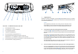
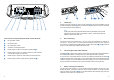
1 Zugentlastung Schließen Sie das Kabel vom Netzteil an der Buchse des Steuersenders SI 1015 an und führen Sie es durch die Zugentlastung . Der Stecker kann so nicht mehr aus der Buchse herausrutschen und den Betrieb unterbrechen. Hinweis Eine Zugentlastung ist besonders dann wichtig, wenn das Gerät fest in einem Rack eingebaut ist.
Elektrisches Zubehör Anschlußkabel GZL 1019 A1 Für den Anschluß des Strahlers an die Sender SI 1015, SI 29-5 oder SI 1029. Länge 1 m. Anschlußkabel GZL 1019 A5 Für den Anschluß des Strahlers an die Sender SI 1015, SI 29-5 oder SI 1029. Länge 5 m. Technische Daten SZI 1015 Leistungsstrahler Anzahl der Sendedioden 66 Mittlere Strahlungsleistung 2W Wellenlänge des abgestrahlten Infrarotlichts ca. 880 nm Trägerfrequenzbereich 30 kHz bis 6 MHz HF - Eingang 50 mV – 5 V / ca.
INSTRUCTIONS FOR USE 10 SI 1015 SZI 1015 11
Connections and operating elements of the SI 1015 (front panel) Connections and operating elements of the SI 1015 (back panel) ON/OFF switch RF output socket 1 for connecting a radiator LED power indicator Overmodulation indicator channel A Barrier strip RF contacts 1 for connecting a radiator (alternative connection to , wired in parallel) Level control channel A Overmodulation indicator channel B Level control channel B Channel sele
1 Cable grip Insert the connector of the plug-in mains unit into socket on the SI 1015 modulator and pass the cable through the cable grip as shown. Because of the cable grip, the connector cannot slip out of the socket and interrupt operation. Note A cable grip is particularly important when the device is permanently rack mounted. Inside the rack there are often a large number of cables – a cable grip prevents the cables from pulling each other out.
Accessoires Technical Data SI 1015 Modulator Operating voltage 24 - 35 V DC (via NT 1015) Current consumption < 140 mA Terminating impedance of the RF outputs 50 Ω Carrier frequency 1 Carrier frequency 2 2.3 MHz 2.8 MHz Inputs 2 x XLR-3, balanced Input sensitivity 50 mV – 5 V RF outputs 2 x BNC, in parallel with barrier strip GZL 1019 A5 BNC/BNC co-axial cable SZI 1015 Power radiator For connecting a radiator to the SI 1015, SI 29-5 or SI 1029 transmitters. Length: 5 m.
NOTICE D‘EMPLOI 18 SI 1015 SZI 1015 19
Commandes et raccordements du SI 1015 (partie frontale) Commandes et raccordements du SI 1015 (partie arrière) Interrupteur Marche/Arrêt Connecteur de sortie HF 1, raccordement pour diffuseur LED tension secteur Bornier de sortie HF 1, raccordement pour diffuseur (en parallèle à ) Indication de surmodulation canal A Bornier de sortie 1 alimentation DC pour diffuseur (chaînage de ) Réglage du niveau canal A Bornier de sortie 2 alimentation D
1 Bride de retenue Insérer le connecteur du bloc-secteur dans la prise du modulateur, puis passer le câble dans la bride de retenue pour éviter toute traction sur la prise. Ceci garantit une fixation de sécurité dans la prise et évite tout risque d’interruption du fonctionnement.
Accessoires Câble de raccordement GZL 1019 A1 Destiné à relier le diffuseur aux émetteurs SI 1015, SI 29-5 ou SI 1029. Longueur: 1 m. Caractéristiques techniques SZI 1015 Diffuseur de puissance Nombre de diodes d’émission 66 Puissance moyenne de rayonnement 2W Longueur d’onde de la lumière infrarouge rayonnée approx. 880 nm Plage de fréquences porteuses 30 kHz – 6 MHz Entrée HF 50 mV – 5 V / approx.
ISTRUZIONI PER L‘USO 26 SI 1015 SZI 1015 27
Collegamento e uso dell‘SI 1015 (parte anteriore) Collegamento e uso dell‘SI 1015 (Parte posteriore) tasto ON / OFF Presa d‘uscita 1 per RF, collegamento del radiatore di potenza LED per il controllo d‘allacciamento alla rete Presa a morsetto 1 per RF, collegamento del radiatore di potenza (collegato in parallelo a ) Indicazione di sovramodulazione canale A Presa 1 collegamento dell‘alimentatore per il radiatore di potenza (collegato in serie con
1 Dispositivo anti trazione Collegate il cavo dell‘alimentatore alla presa del trasmettitore di comando SI1015 e fissatelo nel dispositivo anti-trazione . Si evita cosi che la presa perda il contatto e che il funzionamento venga interrotto. Nota Lo scarico di trazione è di particolare importanza se l‘apparecchio è montato in maniera fissa all‘interno di un rack.
Accessori elettrici Dati tecnici SZI 1015 Radiatore di potenza Numeri dei diodi di trasmissione 66 Potenza irradiata media 2W Lunghezza d‘onda della luce infrarossa irradiata ca.
INSTRUCCIONES PARA EL USO 34 SI 1015 SZI 1015 35
Elementos de conexión y mando del SI 1015 (cara frontal) Elementos de conexión y mando del SI 1015 (cara dorsal) Interruptor principal Jack de salida de AF, conexión para radiador de potencia LED de control de conexión a la red Conexión a presión AF, conexión para radiador de potencia (paralelo a ) Indicación de sobremodulación del canal A Conexión 1, alimentación de corriente para radiador de potencia (paso en bucle desde ) Regulador de niv
1 Dispositivo de contratracción Conecte el cable del bloque de alimentación al jack del transmisor de mando SI 1015; pase el cable a través del dispositivo de contratracción . Esto impide que la clavija pueda salirse del jack, interrumpiéndose el funcionamiento. Nota El dispositivo de contratracción es especialmente importante cuando el equipo ha de montarse fijamente en un bastidor pues, a menudo, en el interior de éste hay muchos cables.
Accesorios eléctricos Cable conector GZL 1019A1 Datos técnicos SZI 1015 Radiador de potencia Número de diodos transmisores 66 Potencia mínima de radiación 2W Longitud de onda de la luz infrarroja irradiada aprox. 880 mm Margen de frecuencia portadora 30 kHz hasta 6 MHz Entrada AF 50 mV - 5 V/aprox.
GEBRUIKSAANWIJZING 42 SI 1015 SZI 1015 43
Aansluit- en bedieningselementen SI 1015 (voorzijde) Aansluit- en bedieningselementen SI 1015 (achterzijde) Aan-/uit-schakelaar HF-uitgangsbus 1, aansluiting voor vermogensstraler Netspanningscontrole LED HF-klemaansluiting 1, aansluiting voor vermogensstraler (parallel aan ?) Overmodulatie-aanduiding kanaal A Aansluiting 1 voedingsspanning vermogensstraler (doorgelust van ?) Niveau-instelling kanaal A Aansluiting 2 voedingsspanning vermogensstr
1 Trekontlasting Steek de netvoedingskabel in de bus van de stuurzender SI 1015 en leid de kabel door de trekontlasting . De stekker kan zo niet meer uit de bus worden getrokken, zodat de werking niet wordt onderbroken. Opmerking Een trekontlasting is vooral van belang, wanneer het apparaat vast in een rack is ingebouwd. Binnenin het rack liggen vaak veel kabels - een dergelijke bevestiging voorkomt, dat de kabels elkaar uit de bussen drukken.
Elektrische accessoires Aansluitkabel GZL 1019 A1 Technische gegevens SZI 1015 Vermogensstraler Aantal zenddioden Gemiddeld uitstralingsvermogen 66 2W Golflengte van het uitgestraalde infraroodlicht ca. 880 nm Draagfrequentiebereik 30 kHz tot 6 MHz HF-ingang 50 mV - 5 V/ca. 5 kΩ Ingang/uitgang BNC-bussen/klemlijsten Schakeldrempel voor inschakelautomaat 50 mV Voedingsspanning 25-35 V gelijkspanning uit voeding NT 1015 of uit stuurzender SI 1015 Stroomopname ca.
Aktuelle Informationen zu Sennheiser-Produkten erhalten Sie auch im Internet unter „http://www.sennheiser.com“. Up to date information on Sennheiser products can also be found on the Internet at “http://www.sennheiser.com”. Konformitätserklärung Sennheiser electronic GmbH & Co. KG erklären, daß dieses Gerät die an-wendbaren CE-Normen und Vorschriften erfüllt. Approval Vous trouverez également toutes les informations actuelles relatives aux produits Sennheiser sur Internet, sous “http://www.sennheiser.com“.
Änderungen vorbehalten Subject to alterations Sous réserve de modification Con riserva di modifiche Reservado el derecho a introducir modificaciones Wijzigingen voorbehouden Sennheiser electronic GmbH & Co. KG D-30900 Wedemark Printed in Germany 52 Publ.