SWL-3000AP Series Access Point User’s Guide * This User’s Guide can be used on SWL-3000AP, 3000AP(DA), 3300AP and 3300AP(DA).
Notice when you establish * We recommend you to avoid this places where may be cause of performance decline or trouble. 1. 2. 3. 4. 5. Places with high humidity or wet condition Places with extreme temperature(too hot or too cold) Places where change of temperature is extreme Places with a lot of dusts Places sealed with thick walls or still structure Notice when you use 1. Do not disassemble on your own. 2. Do not drop the product or give excessive impact. 3. Do not twist or lengthen the power cord. 4.
Table of Contents 1. Introduction⋅⋅⋅⋅⋅⋅⋅⋅⋅⋅⋅⋅⋅⋅⋅⋅⋅⋅⋅⋅⋅⋅⋅⋅⋅⋅⋅⋅⋅⋅⋅⋅⋅⋅⋅⋅⋅⋅⋅⋅⋅⋅⋅⋅⋅⋅⋅⋅⋅⋅⋅⋅⋅⋅⋅⋅⋅⋅⋅⋅⋅⋅⋅⋅⋅⋅ 1 2. Installation⋅⋅⋅⋅⋅⋅⋅⋅⋅⋅⋅⋅⋅⋅⋅⋅⋅⋅⋅⋅⋅⋅⋅⋅⋅⋅⋅⋅⋅⋅⋅⋅⋅⋅⋅⋅⋅⋅⋅⋅⋅⋅⋅⋅⋅⋅⋅⋅⋅⋅⋅⋅⋅⋅⋅⋅⋅⋅⋅⋅⋅⋅⋅⋅⋅⋅⋅⋅ 3 3. AP Basic Setting Using AP Manager⋅⋅⋅⋅⋅⋅⋅⋅⋅⋅⋅⋅⋅⋅⋅⋅⋅⋅⋅⋅⋅⋅⋅⋅⋅⋅⋅ 4. PTP Setting Using AP Manager⋅⋅⋅⋅⋅⋅⋅⋅⋅⋅⋅⋅⋅⋅⋅⋅⋅⋅⋅⋅⋅⋅⋅⋅⋅⋅⋅⋅⋅⋅⋅⋅⋅⋅⋅ 10 5. AML Setting Using AP Manager⋅⋅⋅⋅⋅⋅⋅⋅⋅⋅⋅⋅⋅⋅⋅⋅⋅⋅⋅⋅⋅⋅⋅⋅⋅⋅⋅⋅⋅⋅⋅⋅⋅ 14 6.
13. Firmware Upgrade Using AP Manager ⋅⋅⋅⋅⋅⋅⋅⋅⋅⋅⋅⋅⋅⋅⋅⋅⋅⋅⋅⋅⋅⋅⋅ 52 14. Data Transmission Status Check Using AP Manager⋅ 55 15. AP Setting Using Web Browser⋅⋅⋅⋅⋅⋅⋅⋅⋅⋅⋅⋅⋅⋅⋅⋅⋅⋅⋅⋅⋅⋅⋅⋅⋅⋅⋅⋅⋅⋅⋅⋅⋅ 58 16. AP Setting Using TELNET⋅⋅⋅⋅⋅⋅⋅⋅⋅⋅⋅⋅⋅⋅⋅⋅⋅⋅⋅⋅⋅⋅⋅⋅⋅⋅⋅⋅⋅⋅⋅⋅⋅⋅⋅⋅⋅⋅⋅⋅ 60 17. HyperTerminal Setting for RS-232C(COM Port) Communication⋅⋅⋅⋅⋅⋅⋅⋅⋅⋅⋅⋅⋅⋅⋅⋅⋅⋅⋅⋅⋅⋅⋅⋅⋅⋅⋅⋅⋅⋅⋅⋅⋅⋅⋅⋅⋅⋅⋅⋅⋅⋅⋅⋅⋅⋅⋅⋅⋅⋅⋅⋅⋅⋅⋅⋅⋅⋅⋅ 61 18. AP Basic Setting Using RS-232C(COM Port)⋅⋅⋅⋅⋅⋅⋅⋅⋅⋅⋅⋅⋅ 62 19.
1. Introduction Thank you for purchasing SAMSUNG SWL-3000AP Series Access Point(AP). This guide describes the installation and basic configuration of the Access Point. Standard Model is SWL-3300AP for example.
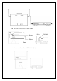
! The Front and Rear View of SWL-3300AP Status Wireless DC in RS-232C RJ-45 Connector Ethernet Power ! The Front and Rear View of SWL-3300AP(DA) 2
2. Installation ① Choose the place with the consideration of power outlet and network connection (RJ-45 Cable connection) to install the Access Point. ② Plug in the power cord to the power outlet and the power adapter. Plug in the DC output to “DC in”. Make sure that the “Power” LED is on. If the “Power” LED is not on, please check the connections of the power cord. Notice : Use the supplied power adapter(DC 5V, 2A) only to prevent the permanent failure of AP. ③ Confirm that “Wireless” LED of AP blinks.
⑧ Insert Wireless LAN Card into your PC. Wireless LAN Cards are available both for desktop and notebook PCs. PCI Wireless LAN Card is used for the desktop PC where as the PCMCIA Wireless LAN Card is for the notebook PC only. For more information about PCI and PCMCIA Wireless LAN Cards, please visit http://www.magiclan.com. ⑨ Enter the same ESSID that you have set for the Access Point, using the Wireless LAN Card utility running on your PC.
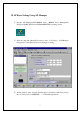
3. AP Basic Setting Using AP Manager ① Execute AP Manager(SWL-3000AP Series, 4000AP Series Management Utility) under MS-Windows 95/98/Me/2000/NT/XP operating system. ② After choosing AP, which will be used by users, on “List Box” of AP Manager using mouse, select [Basic] tab for any changes on setting. ③ AP information of the selected AP will appear on [Selected AP’s Info] Group Box. You may refer to APPENDIX Ⅰ for detailed explanation.
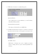
④ TCP/IP address environment is set on [Basic] Dialogue Box. ♦ Specify an IP address After consulting with your system administrator, you enter IP Address, Subnet Mask and Gateway Address. ♦ Obtain an IP address automatically This setting is possible when AP is used for DHCP Client. ⑤ Set ESSID and Channel number. Description is a parameter not related with any operation, and it is used only to record description or stored location of AP. ♦ Set ESSID for AP use. ESSID (Max.
♦ Set Channel for AP use. Channel index should be between 1 and 14(differs from country to country). Notice : If you are operating two or more Access Points in the adjoining cells, keep the appropriate channel distance to avoid the interference. We recommend you to keep the distance of at least 4 channels in the adjoining cells. ⑥ Select “Change Password” on [File] menu if you want to change the password. ⑦ After entering Current Password, New Password and Retype Password, click [OK] button.
⑧ When you click [Confirm & Apply] button to apply new configuration, “Configuration Summary” window, which shows new configuration, will appear. Confirm New Configuration ⑨ If new settings are entered correctly, click [Apply] button to apply new configuration. ⑩ When you click [Apply] button, “Password” window will appear. The default password is “public”, and user can change password later.
⑪ After you enter the password, click [OK] button. ⑫ If you want to set default values, click [Load Default values] button. Then, AP Configuration will return to default setting.
4. PTP Setting Using AP Manager ① PTP stands for Point to Point, and it is used to connect two divided networks into one using AP as Wireless Bridge. In this case, AP cannot be used for capabilities of Access Point. X-Cable Internet Network (Hub) < Wired Network Using Hub> < Point to Point Area> < Wireless Network Using AP> ② After executing AP Manager, select [Radio] tab on “Tab Bar”. Select AP to set PTP on “List Box” using mouse, and confirm setting status on [Radio] Dialogue Box.
③ When Operation Mode of AP is selected for “Point-to-Point” on [Radio] Dialogue Box, [Remote ID (PTP)] Box will appear to enter MAC ID of Wireless LAN Card on other AP, which will be connected by using PTP mode. Setting MAC ID of other Wireless LAN Card to be Connected Using PTP Mode ④ When [Edit] button on [Remote ID (PTP)] Box is selected, [MAC ID] Box, which is to enter(for entering) MAC ID of Wireless LAN Card of other AP to be connected, will appear.
Confirm MAC ID Setting of other Wireless LAN Card to be connected using PTP Mode ⑤ ESSID and Channel of two APs must be identical in PTP mode Enter the Same ESSID and Channel of two APs in PTP Mode ⑥ When you click [Confirm & Apply] button to apply new configuration, “Configuration Summary” window, which shows new configuration, will appear.
Confirm Common ESSID and Channel for AML Mode Setting Confirm AML Mode Setting ⑦ If new settings are entered correctly, click [Apply] button to apply new configuration. ⑧ When you click [Apply] button, “Password” window will appear. ⑨ After you enter the password, click [OK] button. ⑩ When you click [Apply] button instead of [Confirm & Apply] button, “Password” window will appear immediately skipping “Configuration Summary” window.
new configuration. ⑪ After rebooting, choose selected proper AP on “List Box”. Then, the selected AP set with PTP Mode can be confirmed on [Selected AP’s Info] Group Box as shown below.
5. AML Setting Using AP Manager ① AML stands for Automatic Multi-link. Using AP as Wireless Bridge, it is used to connect several divided networks into one. It connects several [Slave]s with one main [Master]. < Wired and Wireless Network using Hub and AP> (Hub) Internet Network [Master] Internet Network X-Cable (Hub) [Slave] [Slave] ② After executing AP Manager, click [Radio] tab on “Tab Bar”.
④ Select either “Master” or “Slave” for [Control Mode] on [Automatic Multi-link] Box. Basically, AML Mode consists of two or more APs, and set one for “Master” and the rest for “Slave”s.
⑤ All of ESSID and Channel of AP set in AML mode must be identical. Enter the Same ESSID and Channel of all APs in AML Mode ⑥ When you click [Confirm & Apply] button to apply new configuration, “Configuration Summary” window, which shows new configuration, will appear. Confirm Common ESSID and Channel for AML Mode Setting Confirm AML Mode Setting ⑦ If new settings are entered correctly, click [Apply] button to apply new configuration. ⑧ When you click [Apply] button, “Password” window will appear.
⑨ After you enter the password, click [OK] button. ⑩ When you click [Apply] button instead of [Confirm & Apply] button, “Password” window will appear immediately skipping “Configuration Summary” window. After you enter the password, click [OK] button to apply new configuration. ⑪ After rebooting, choose selected proper AP on “List Box”. Then, the selected AP set with AML Mode can be confirmed on [Selected AP’s Info] Group Box as shown below.
6. Bridge Table and Protocol Management Using AP Manager ① Using AP Manager, list of Wired and Wireless Station(PC or AP) connected to current AP can be confirmed. Also, it sets type of Protocol to receive and send selected data, which satisfy Protocol user wants, among data transmitting through AP. ② When you select [Bridge] tab on “Tab Bar” of AP Manager, two boxes, which manage “Bridge Table” and “Protocol” on Dialogue Box, will appear.
④ [Age Time] on [Bridge Table] Management Box shows cycle of AP refreshing “Bridge Table”. The use of Default Values is recommended. ⑤ After selecting Station Type you want with Radio button to refresh Stations connected to current AP, click [Refresh Bridge Table] button to confirm.
Select “Enabled” Select Protocol Which You Do Not Want ⑩ If new settings are entered correctly, click [Apply] button to apply new configuration. ⑪ When you click [Apply] button, “Password” window will appear. ⑫ After you enter Password, click [OK] button.
7. NAT Setting Using AP Manager ① NAT stands for Network Address Translation, and it is used to establish private network domain. Using NAT, any desktop or notebook PC, which are connected to AP, may freely use any private IP Address. In this case, the private IP Address must have same Network Address assigned for NAT IP Address. For Example) NAT IP Address : 172.16.0.1 Station IP Address #1 : 172.16.0.100 Station IP Address #2 : 172.16.0.150 In this case, Network Address is 172.16.0.X.
③ When you click [Confirm & Apply] button to apply new configuration, “Configuration Summary” window, which shows new configuration, will appear. Confirm NAT Setting ④ If new settings are entered correctly, click [Apply] button to apply new configuration. ⑤ When you click [Apply] button, “Password” window will appear. ⑥ After you enter the password, click [OK] button.
⑦ When you click [Apply] button instead of [Confirm & Apply] button, “Password” window will appear immediately skipping “Configuration Summary” window. After you enter the password, click [OK] button to apply new configuration. ⑧ After rebooting, choose selected proper AP on “List Box”. Then, the selected AP set with NAT can be confirmed on [Selected AP’s Info] Group Box as shown below. Confirm NAT Setting ⑨ Configuration of Desktop or notebook PC to connect with AP under MSWindows is shown below.
Select “TCP/IP” [Properties] of LAN Adapter to use on [Configuration] Menu. Set “IP Address” and “Subnet Mask” on [IP Address] Menu. In this case, IP Address entered on “IP Address” must have same Network Address of IP Address of AP assigned for NAT.(Refer step ①.
Gateway Address must have same as “IP Address” of AP assigned by NAT Setting on “New Gateway” of [Gateway] Menu. Configuration has been completed for desktop or notebook PC to connect with AP. In this case, the specified IP Address of desktop or notebook PC should have same network address as set by NAT setting.(Refer step ①.
8. DHCP Server Setting Using AP Manager ① DHCP stands for Dynamic Host Configuration Protocol, it is protocol that enables Network administrator to manage and assign IP Address in system centrally. DHCP manages and assigns IP Address for network administrator, and it enables computer to get assigned IP Address when it is connected to other place in the network. However, any changes of IP Address of Web server and FTP server may cause confusion.
Scope of IP Address Assignable Lease Time for Assigned IP Address Assessed Information with IP Address Notice : When you select DHCP Server, the values on the window show information assigned to DHCP Client with IP Address. In most cases, values of “Gateway” and “Submask” are same as those of Gateway and Submask of current AP. ④ Click [Edit IP Scope] button, and the window below will appear.
⑤ To set the scope of assignable IP Address, first check on [Empty] check box on the left. Then, “Empty” will be changed to “Valid”, and you can set the scope. ⑥ Enter the beginning value in “From”, and ending value in “To”. ⑦ When you complete to set the scope of assignable IP Address, click [Clear IP Allocation Table] button to current “Allocation Table”. Then, click [OK] button.
⑪ After you enter the password, click [OK] button. ⑫ When you click [Apply] button instead of [Confirm & Apply] button, “Password” window will appear immediately skipping “Configuration Summary” window. After you enter the password, click [OK] button to apply new configuration. ⑬ After rebooting, choose selected proper AP on “List Box”. Then, the selected AP set with DHCP Server can be confirmed on [Selected AP’s Info] Group Box as shown below.
Notice : If you want to set DHCP Client instead of DHCP Server, select [Basic] on “Tab Bar” menu of AP. Then, select “Obtain an IP address automatically” from Dialogue Box. (Refer to step ④ of Chapter6.) Then, the selected AP gives up its own IP Address, and other AP using DHCP Server will assign it. When the setting is completed, click [Confirm & Apply] or [Apply] button to apply new configuration.
9. NAT and DHCP Server Simultaneous Setting Using AP Manager ① After executing AP Manager, select [Server] tab on “Tab Bar” to set DHCP Server and NAT simultaneously. ② Please refer to Chapter 10 for NAT Setting and Chapter 11 for DHCP Server Setting. This chapter shows default values. Server Setting DHCP Server Setting Refer to Notice NAT Setting Notice : In this case, IP Address as Gateway format in NAT Setting must be set for Gateway of DHCP Server Setting.
③ When you click [Confirm & Apply] button to apply new configuration, “Configuration Summary” window, which shows new configuration, will appear. Confirm NAT and DHCP Setting ④ If new settings are entered correctly, click [Apply] button to apply new configuration. ⑤ When you click [Apply] button, “Password” window will appear. ⑥ After you enter the password, click [OK] button.
⑦ When you click [Apply] button instead of [Confirm & Apply] button, “Password” window will appear immediately skipping “Configuration Summary” window. After you enter the password, click [OK] button to apply new configuration. ⑧ After rebooting, choose selected proper AP on “List Box”. Then, the selected AP set with NAT and DHCP Server can be confirmed on [Selected AP’s Info] Group Box as shown below.
10. ADSL and Cable Modem Connection Setting Using AP Manager ① After executing AP Manager, click [Advanced] and [Internet Connection] on “Menu Bar” in the following order. Or click [Internet Connection] button on [Basic] Dialogue Box. Select on “Menu Bar” Select on “Dialogue Box” ② Then the Internet Connection Setup page(default page) will appear.
Notice: ADSL can generally be divided into two service types supporting PPPoE or PPTP, but PPPoE is more common. If you don’t know your ADSL service type, please check the Website or contact your ISP to find out service type you are using. ③ Go to 10.1 for PPPoE, 10.2 for PPTP, and 10.3 for Cable Modem 10.
③ Set NAT and DHCP Server referring Chapter 9. DHCP Server and NAT Setting ④ Click [Finish] button to complete setting.
⑤ A window will appear and ask you to apply new settings immediately. If you do not want to apply new settings, select [No(N)]. ⑥ If you click [Yes(Y)] button, “Password” window will appear. After you enter the password, click [OK] button to apply. In case you select [No(N)] button, new settings will be saved. If you want to continue applying procedure again, click [Apply] button on “Button Bar”. ⑦ When you click [Basic] tab on “Tab Bar,” ADSL Connection Status will appear in Dialogue Box.
10.2 Settings for ADSL – PPTP ① When the above page appears, enter the user name given by your ISP(Internet Service Provider) in the “User Name” box. ② Enter the password in the “Password” box. ③ Enter the IP Address of PPTP Server in the “PPTP Server IP Address” box Notice: In case IP Address of PPTP Server are unknow, contact your ISP.
④ Set NAT and DHCP Server referring Chapter 9. Setting DHCP Server and NAT ⑤ Click [Finish] button to complete setting.
⑥ A window will appear and ask you to apply new settings immediately. If you do not want to apply new settings, select [No(N)]. ⑦ If you click [Yes(Y)] button, “Password” window will appear. After you enter the password, click [OK] button to apply. In case you select [No(N)] button, new settings will be saved. If you want to continue applying procedure again, click [Apply] button on “Button Bar”. ⑧ When you click [Basic] tab on “Tab Bar,” ADSL Connection Status will appear in Dialogue Box.
10.3 Settings for Cable Modem ① Set NAT and DHCP Server referring Chapter 9. Setting DHCP Server and NAT Notice : Personal Information Setting is not needed because Cable modems are generally given with fixed IP Address. ② Click [Finish] button to complete setting.
③ A window will appear and ask you to apply new settings immediately. If you do not want to apply new settings, select [No(N)]. ④ If you click [Yes(Y)] button, “Password” window will appear. After you enter the password, click [OK] button to apply. In case you select [No(N)] button, new settings will be saved. If you want to continue applying procedure again, click [Apply] button on “Button Bar”.
11. Encryption Setting Using AP Manager ① After executing AP Manager, select [Security] tab on “Tab Bar” to set encryption. Then, select “Encryption”. ② Select either “64(40)-bit Key” or “128-bit Key.” The window below shows “64(40)-bit Key” setting. Select Encryption Start Encryption Setting ③ When you select [Set WEP Key] button, a window for WEP Key generation is created as shown below.
④ Enter the agreed password phrase to set encryption in “Passphrase,” and click [Generate] button to create WEP Key. Enter Password Phrase WEP Key Generation Setting “Key 1” among Generated Default Key Values After generating the keys, select one key among “Default Key”s. Click [OK] button to complete setting of the key to be used for encryption. Notice : In this case, WEP Keys should be generated using same Passphrase for Card Utility of desktop and notebook PC.
Confirm 64(40)-bit Encryption Setting ⑥ If new settings are entered correctly, click [Apply] button to apply new configuration. ⑦ When “Password” window appear, enter the password. Then click [OK] button. ⑧ After rebooting, choose selected proper AP on “List Box”. Then, the selected AP set with Encryption can be confirmed on [Selected AP’s Info] Group Box as shown below.
12. User Access Control Setting Using AP Manager ① “User Access Control” is function that shows permission of using AP to MAC ID Table of Wireless LAN Card installed on certain Stations among desktop or notebook PC, which are connected AP. If you want to use this function, select “User Access Control” on [Security] Dialogue Box.
Select Connection Deny Click [+] icon, and enter MAC ID as shown on the window below. Then, click [OK] button to add MAC ID on [Allowed Table].
⑥ When you want to deny specific MAC ID and permit the other, select “pass” on [Other Stations] Box. Then, add the MAC ID on [Denied Table], which is you want to deny. MAC ID can be entered by the method explained on ⑤ and also move MAC ID from [Allowed Table]. ⑦ To move MAC ID from [Allowed Table] to [Denied Table], use [>>] icon. Otherwise, use [<<] icon. ⑧ After select “pass” on [Other Stations] Box, move MAC ID from [Allowed Table] to [Denied Table] using [>>].
⑨ If you want to export and save MAC IDs registered either on [Allowed Table] or [Denied Table], click [Export] button. Then, it will be saved where user wants as “granted.lst” or “denied.lst”. You can rename the file name. # granted.lst -> MAC ID List on [Allowed Table] # denied.lst -> MAC ID List on [Denied Table] Save MAC ID File name.lst On the other hand, click [Import] button to import saved MAC ID Lists.
⑩ You can combine and use various settings as you wish. ⑪ If new settings are entered correctly, click [Apply] button to apply new configuration. ⑫ When “Password” window appear, enter the password. Then, click [OK] button.
13. Firmware Upgrade Using AP Manager ① Whenever the new version of AP Firmware is available, you can upgrade AP firmware into higher version using AP Manager. ② After executing AP Manager, select [Firmware] tab on “Tab Bar”. ③ Dialogue Box of the Firmware upgrade is like what is view in the window below. ④ The current firmware information of the selected AP is displayed in the [Version Information] Box as shown in the window below.
⑤ Downloaded the latest version of AP firmware in local disk of your PC Notice: AP firmware corresponding to your AP can be downloaded in MagicLAN home page. ⑥ Click the file icon shown below on Dialogue Box. ⑦ After select the firmware image file, click [Open] button.
⑧ Click the [Load] button after the file is selected. Then, “Password” window will be displayed. ⑨ Enter the password, default password is “public”, and click [OK] button. The AP firmware is loaded from your Local Disk to the Access Point and is upgraded. The following window shows the status of loading the AP firmware image file to the AP. Click the [Stop] button to cancel the download of AP firmware at any time. An error message will show up if AP firmware other than you select is downloaded.
14. Data Transmission Status Check Using AP Manager ① Data transmission traffic status of current AP can be confirmed using AP Manager. ② When [Statistics] tab on “Tab Bar” of AP Manager is selected, a window, which shows [Traffic Selection] Box on Dialogue Box to select Traffic type and shows related information below, will appear.
⑤ If you want to confirm with line graph, select “Line” instead of “Histogram” on Related Information Confirm Box. Line Setting ⑥ In this case, if confirm is impossible due to increased number of packets with wired and wireless transmission, increase scope of number of packet transmitted per second(packet/sec) to confirm.
# SNMP : Simple Network Management Protocol # MIB : Management Information Base Select MIB Type Related Information Confirm Box ⑨ Confirming Traffic information you want enables more efficient AP operation.
15. AP Setting Using Web Browser ① Open Web Browser. (Beyond IE 4.0 or Netscape 4.0) ② Enter AP’s IP Address on “Address” of the Web Browser. Press [ENTER : ↵] key. ③ “Enter Network Password” window appears. Do not enter the User Name. Enter the password. (The default value is “public”, and user can change the password later) Click [OK] button. Notice : Capital•Small letter distinction is recommended for the password.
④ Internet Connection Setting page”(default page) appears. ⑤ Simple Configuration Mode is for Setting of Internet Connection Environment, and refer to “10. ADSL and Cable Modem Connection Setting Using AP Manager”. ⑥ Expert Mode is for Network Administration, and refer to “3. AP Basic Setting Using AP Manager”.
16. AP Setting Using TELNET ① Open “Run” on [Start] menu of desktop and notebook PC. Enter the IP Address for Internet Connection as following Example. Example) telnet ***.***.***.*** (IP Address ) Click [OK] button. ② Telnet order window appears, and please refer to “18.
17. HyperTerminal Setting for RS-232C(COM Port) Communication ① Execute the HyperTerminal under MS-Windows 95/98/Me/2000/NT/XP operating system by following the steps below. Execute Hypertrm.exe file in “HyperTerminal” folder. ② After executing the Hypertrm.exe file, the following window will be displayed on MS-Windows.
③ As displayed above, type “AP MANAGER” in the name field, and click [OK] button. You can enter any name you wish for the connection. ④ Select the modem port as shown in the window below, and click [OK] button. (In most of the cases, select either “Direct to Com1” or “Direct to Com2”.) ⑤ You will view the following window and must set the properties of the selected COM port as shown below. Click [OK] button, and then press [ENTER : ↵].
⑥ If all the steps above are executed correctly, then the following menu will be displayed on the HyperTerminal window. The default password is “public”, and user can change password later. ================================================== Samsung SWL-3300AP Configuration ================================================== To configure the Access Point, the password is required. Enter password : ⑦ When the password is entered, the following [ROOT] menu appears on the HyperTerminal window.
18. AP Basic Setting Using RS-232C(COM Port) ① Choose [Basic] menu on [ROOT] menu. ================================================== Samsung SWL-3300AP Configuration ================================================== [ Basic ] 1. ESSID 2. Channel 3. DHCP Client 4. IP Address 5. Subnet Mask 6. Gateway Address 7. Description CMD(t,p,h): MagicLAN 3 Disabled 10.0.0.2 255.255.255.0 10.0.0.1 MagicLAN 11Mbps AP Enter Menu Number ② Select the following order to set Wireless LAN ESSID.
③ Select the following order to change Wireless Channel. CMD(t,p,h): 2 ↵ Enter new Channel {1-14}: 11 Enter Current Channel ↵ Enter the proper channel number after the phrase “Enter new Channel {114}:”. Then, press [ENTER : ↵]. Channel index should be between 1 and 14(differs from country to country). Notice : If you are operating two or more Access Points in the adjoining cells, keep the appropriate channel distance to avoid the interference.
⑥ Select the following order to set Subnet Mask. CMD(t,p,h): 5 ↵ Enter Subnet Mask Enter new Subnet Mask : 255.255.255.0 ↵ Enter the proper subnet mask after the phrase “Enter new Subnet Mask :”. Then, press [ENTER : ↵]. Consult your system administrator for setting the subnet mask. ⑦ Select the following order to set Gateway Address. CMD(t,p,h): 6 ↵ Enter Gateway Address Enter new Gateway Address : 16.3.60.1 ↵ Enter the proper Gateway Address after “Enter new Gateway Address :” .
⑨ If you want to change Password, select the following order on [ROOT] menu. ================================================== Samsung SWL-3300AP Configuration ================================================== [ ROOT ] 1. Basic [Menu] 2. Advanced [Menu] 3. Server [Menu] 4. Status [Menu] 5. Load default values 6. Save and reboot Select Advanced CMD(t,p,h): 2 ↵ Select [Administration] menu on [Advanced] Menu.
================================================== Samsung SWL-3300AP Configuration ================================================== [ Administration ] 1. Password activity 2. Change password CMD (t,p,h): 2 Enabled ↵ Enter Current Password Enter current password (Max. 30 characters):****** ↵ Enter New Password Enter new password (Max. 30 characters):****** Enter new password again:****** ↵ ↵ Confirm New Password Enter the current password (Max. 30 characters) after “Enter current password (Max.
⑩ You must select “Save and reboot” on [ROOT] menu, after changing the appropriate parameters by entering the new values. ================================================== Samsung SWL-3300AP Configuration ================================================== [ ROOT ] 1. Basic [Menu] 2. Advanced [Menu] 3. Server [Menu] 4. Status [Menu] 5. Load default values 6. Save and reboot Select Save and reboot CMD(t,p,h): 6 ↵ By selecting the above menu, rebooting will occur automatically.
⑪ After following all the steps mentioned above, you can close the HyperTerminal window if there is no need for change or setting. Select [Basic] menu if you want to confirm the settings. ================================================== Samsung SWL-3300AP Configuration ================================================== [ Basic ] Confirm Configuration 1. ESSID test_AP 2. Channel 11 3. DHCP Client Disabled 4. IP Address 16.3.60.208 5. Subnet Mask 255.255.255.0 6. Gateway Address 16.3.60.1 7.
19. Load default values Using RS-232C(COM Port) ⑫ Select “Load default values” on [ROOT] menu ================================================== Samsung SWL-3300AP Configuration ================================================== [ ROOT ] 1. Basic 2. Advanced 3. Server 4. Status 5. Load default values 6. Save and reboot CMD(t, p, h): 5 [Menu] [Menu] [Menu] [Menu] Select“Load Load Default values” values All configured items will be set to the default values.
20. Firmware Upgrade Using RS-232C(COM Port) ① Click the “Hyperterminal icon” saved in hard disk of your PC’ ② “Enter password” menu will be displayed on the HyperTerminal window. The default password is “public”, ③ When the password is entered, [ROOT] menu appears on the HyperTerminal window. ④ Downloaded the latest version of AP firmware in local disk of your PC Notice: AP firmware corresponding to your AP can be downloaded in MagicLAN home page.
AP Firmware can be upgraded via serial using 1k-xmode protocol. Power must be always on during the upgrade. Do you really want to upgrade the firmware via serial ? (y/n):y ↵ Do you really want (y/n)? y ⑥ If you want to upgrade the AP firmware, enter “y(yes)” after “Do you really want to upgrade the firmware via serial ?” then, press [Enter:↵]. Enter “y(yes)” again after “Do you really want (y/n)?”, then press [Enter:↵]. The following window will be displayed.
⑧ Select [transfer] menu on “Menu Bar” then, select “Send File“. ⑨ Click [Browse] button on the “Send File” window ⑩ After select the firmware image file on opened window, click [Open] button.
⑪ “1K Xmodem” should be selected on Protocol, then click [send] button. 1K Xmodem The following window shows the status of loading the AP firmware image file to the AP. Notice: An error message will show up if AP firmware is not corresponding to your AP. ⑫ Firmware upgrade using RS-232C is recommended, only when “AP Manager” can not be used.
APPENDIX Ⅰ. Explanation of Basic Configuration to use AP Manager # Explanation of AP External Icons DC 5V Power LED(Green), it is always on. IEEE 802.3 Wired LAN Connection LED(Orange), it is always on. IEEE 802.11 Wireless LAN Connection LED(Green), it blinks. Status LED(Red) - firmware upgrade / error occur # Explanation of Detailed Names and Icons of AP Manager This “AP Manager Execution Icon” appears on Desktop(under MS-Windows) of desktop and notebook PC.
Menu Bar Tab Bar List Box Dialogue Box Button Bar The window above shows “AP Manager” window. You can select menu from this “Menu Bar”. You can select each function of AP setting tabs on this “Tab Bar”. The very left icon shows currently selected tab. This “LED icon” shows Sending and Receiving status of AP and Transmission status of ADSL. Sending, Receiving, and ADSL Transmission Status are shown on order.
Selected AP IP Address of Selected AP MAC Address of Selected AP Channel Index of Selected AP Server Operation Status of Selected AP Operation Mode of Selected AP Encryption Setting Status of Selected AP “List Box” shows Access Points connected to same network segment, and “Selected AP’s Info” shows simple information of selected AP. ADSL Connection Status “Dialogue Box” is area for reading and writing setting values of AP.
This “Button Bar” consists of buttons showing AP Scan, Entering setting values, AP information and AP Manager information. AP Search Erase Window AP Search Cycle This is “AP Monitor Window” when you click [Mode] button from “Button Bar”. It shows APs connected around. Click [Mode] button to return to AP Manager mode. The window above is “Start IP Address Window” when you select [Search] button from “AP Monitor Window”.
The window above shows “Configuration Summary”, and it appears when you select [Confirm & Apply] button. This is “Password Window” for user authentication. Click [Apply] button to open this window.
APPENDIX Ⅱ. Specification General Wireless Network IEEE 802.11b(DSSS) Architecture Wired Network Architecture Ethernet (10/100Mbps) Power Adapter 90 ~ 265VAC 47/63 Hz to 5VDC 2A Certifications EMC Emission : - FCC Part 15 Class B - EN 55022 Class B EMC Immunity : EN 50082-1 IEEE 802.11 Features Data Rates - 1Mbps, 2Mbps, 5.
Management Features Local Configuration Serial EIA-232 Remote Configuration - HTTP, Telnet, SNMP supported - AP Manager for Microsoft Windows 95/98/2000/NT Firmware Upgrade Upgrading via Serial/Ethernet Interface supported Automatic Searching AP Easy to search the AP using AP Manager without knowing AP's IP Address SNMP Compliance MIB I, II and 802.
Environmental Information Operating Temperature ℃ to 45℃ 0℃ ℉ to 113℉) (32℉ Storage Temperature ℃ to 70℃ ℃ -25℃ ℉ to 158℉ ℉) (-13℉ Humidity 95% Non-condensing Physical Characteristics WLAN Interface PCMCIA Release 2.1 (3.
We value your feedback. If you find errors or omissions in this manuscript, or if you can suggest ways to improve its usefulness, we would be pleased to hear from you. Please contact us at : E-mail: wlanap@samsung.co.kr You can find the latest firmware, software, and documents at: http://www.magiclan.