PCA-6189 Full-sized PCI/ISA-bus socket 479 Pentium® M/ Celeron® M processor-based CPU card User’s Manual
Copyright Notice This document is copyrighted, 2005, by Advantech Co., Ltd. All rights are reserved. Advantech Co., Ltd. reserves the right to make improvements to the products described in this manual at any time without notice. No part of this manual may be reproduced, copied, translated or transmitted in any form or by any means without the prior written permission of Advantech Co., Ltd. Information provided in this manual is intended to be accurate and reliable. However, Advantech Co., Ltd.
1.0.1 A Message to the Customer Advantech customer services Each and every Advantech product is built to the most exacting specifications to ensure reliable performance in the harsh and demanding conditions typical of industrial environments. Whether your new Advantech equipment is destined for the laboratory or the factory floor, you can be assured that your product will provide the reliability and ease of operation for which the name Advantech has come to be known.
PCA-6189 User’s Manual iv No No Dual Channel Ultra 160 SCSI: Adaptec 7899 No No Yes LAN 1: Intel 82551QM 10/ 100Base-T 2 LAN 2: Intel 82541 No 10/100/1000Base-T 2 USB 2.0 port Yes Yes Yes VGA: Intel 855GME integrated PCA-6189VG-00A2 LAN 1: Intel 82541 No 10/100/1000Base-T PCA-6189VE-00A2 Model Table 1.
Table 1.2: PCA-6189 DDR memory compatibility table Vendor Size Speed Type ECC Model Memory Apacer 256MB DDR266 DDR N 77.10603 .112 Infineon HYB25D25680B T-7(32×8) Kingston 256MB DDR266 DDR N NA Nanya NT5DS32MBAT6 256MB DDR266 DDR N "KVR256 X64C25/ 256 "Kingston D328DM60(32×8) 512MB DDR266 DDR N KVR266 X64C25/ 512 Kingston D328DL60(32×8) 512MB DDR266 DDR N 990500630.
Samsung(DSL) 512MB DDR400 DDR N NA SAMSUNG K4H560838FTCCC(32×8) Kingston 256MB DDR400 DDR N KVR400 X64C3/ 256 Hynix HY5DU56822BTD43(32×8) UG 1GB DDR266 DDR N NA Hynix HY5DU128822A T-H Apacer 512MB DDR333 DDR N 77.10728 .56G Mosel V58C2256804SA T5B DSL 512MB DDR333 DDR N NA SAMSUNG K4H560838FTCB3 1GB DDR333 DDR N NA SAMSUNG K4H510838BTCB3 Transcend 1GB DDR333 DDR N NA SAMSUNG K4H560438ETCB3 Apacer 256MB DDR400 DDR N 77.10636 .
DSL 256MB DDR400 DDR N NA Hynix HY5DU56822BTD43 256MB DDR400 DDR N NA SAMSUNG K4H560838ETCCC Kingston 256MB DDR400 DDR N KVR400 X72C3A/ 256 Hynix HY5DU56822CT -D43 Transcend 1GB DDR400 DDR N NA SAMSUNG K4H510838BTCCC Apacer 512MB DDR333 DDR Y 77.10735 .114 Infineon HYB25D256800 BT-6 512MB DDR333 DDR Y 77.10735 .464 SAMSUNG K4H560838ETCB3 1GB DDR333 DDR Y 77.11135 .464 SAMSUNG K4H510838BTCB3 512MB DDR400 DDR Y 77.10738 .
1.0.1 Product warranty Advantech warrants to you, the original purchaser, that each of its products will be free from defects in materials and workmanship for two years from the date of purchase. This warranty does not apply to any products which have been repaired or altered by persons other than repair personnel authorized by Advantech, or which have been subject to misuse, abuse, accident or improper installation.
1.0.
1.0.3 Release Note Date Revision Description December 2004 1st.
Important Safety Information SAFETY INSTRUCTIONS This device complies with the requirements in part 15 of the FCC rules: Operation is subject to the following two conditions: 1. This device may not cause harmful interference, and 2. This device must accept any interference received, including interference that may cause undesired operation This equipment has been tested and found to comply with the limits for a Class A digital device, pursuant to Part 15 of the FCC Rules.
PCA-6189 User’s Manual xii
Contents Chapter 1 Hardware Configuration .................................2 1.1 1.2 1.3 Introduction ....................................................................... 2 Features ............................................................................. 3 Specifications .................................................................... 3 1.3.1 1.3.2 1.3.3 1.3.4 1.3.5 1.3.6 1.3.7 1.3.8 1.4 System............................................................................. 3 Memory.............
2.5 2.6 2.7 2.8 2.9 2.10 2.11 2.12 2.13 2.14 USB Ports CN6, CN31, and CN32 ................................. 21 VGA Connector CN7 ...................................................... 22 LVDS connector VCN2 .................................................. 22 DVI connector VCN3...................................................... 23 Ethernet Connector (CN8 and CN34) ............................. 23 Serial Ports (COM1 : CN9; COM2 : CN10 ) .................. 24 PS/2 Keyboard/Mouse Connector (CN11/CN33) ..
3.4.14 3.4.15 3.4.16 3.4.17 3.4.18 3.4.19 3.4.20 3.5 Typematic Delay (msec)............................................... 35 Security Option ............................................................. 36 APIC Mode ................................................................... 36 MPS Version Control For OS....................................... 36 OS Select For DRAM > 64MB .................................... 36 Report No FDD For WIN 95 ........................................
3.9.1 3.9.2 3.9.3 3.9.4 3.9.5 3.9.6 3.9.7 3.9.8 3.9.9 3.9.10 3.9.11 3.9.12 3.9.13 3.10 On-board FDC Controller............................................. 43 On-board Serial Port 1 .................................................. 43 On-board Serial Port 2 .................................................. 43 UART Mode Select ...................................................... 43 RxD, TxD Active.......................................................... 43 IR Transmission Delay .......................
3.13.1 Auto-detect PCI CLK ................................................... 48 3.13.2 Spread Spectrum ........................................................... 48 3.14 Passwords and Settings ................................................... 49 3.14.1 3.14.2 3.14.3 3.14.4 3.14.5 Chapter 4 Chipset Software Install Utility.....................52 4.1 4.2 4.3 Chapter Introduction ..................................................................... 70 Understanding SCSI..............................
10.1 10.2 Introduction ..................................................................... 94 Entering Setup ................................................................. 94 10.3 Array Configuration Utility............................................. 95 Figure 10.1:RAID Setup initial screen ......................... 94 10.3.1 10.3.2 10.3.3 10.3.4 10.3.5 10.3.6 10.4 Figure 10.2:SATA RAID Setup Main Menu screen..... 95 Managing Arrays ..........................................................
B.13 External Speaker Connector (CN17)............................. 117 B.14 Reset Connector (CN18) ............................................... 118 B.15 ATX Feature Connector (CN20)................................... 118 B.16 ATX Feature Connector (CN20)................................... 119 B.17 ATX Soft Power Switch (CN21) .................................. 119 B.18 H/W Monitor Alarm (CN22)......................................... 120 B.19 SM Bus Connector (CN29) ........................
PCA-6189 User’s Manual xx
CHAPTER 1 General Information 1
Chapter 1 Hardware Configuration 1.1 Introduction The PCA-6189 is designed with Intel® 855GME chipset and 6300ESB (I/O controller) to support the Intel® Pentium® M / Celeron® M processor, high speed DDR333 memory, and high performance I/O functions such as dual Gigabit Ethernet ports, Serial/parallel ATA ports, and a PCIX (64-bit / 66Mhz) bus. With the compliance with PICMG 1.
Note: Some of the features mentioned above are not available with all models. For more information about the specifications of a particular model, see Table 1.1 : Comparison table and Section 1.3: Specifications. 1.2 Features 1. Supports FSB 400 MHz low thermal profile Intel® Pentium® M processor or Intel® Celeron® M processor 2. Supports 2 Serial-ATA devices with Software RAID 0 or 1 functions 3. Supports DDR 200/266/333 SDRAM up to 2GB 4.
• Floppy disk drive interface: Supports up to two floppy disk drives, 5¼" (360 KB and 1.2 MB) and/or 3½" (720 KB, 1.44 MB). BIOS enabled/disabled 1.3.2 Memory • RAM: Up to 2 GB in two 184-pin DIMM sockets. Supports DDR266/ 333 SDRAM 1.3.3 Input/Output • Bus interface: PICMG 1.0 compliant PCI/ISA bus interface • Enhanced parallel port: Configurable to LPT1, LPT2, LPT3, or disabled. Standard DB-25 female connector provided.
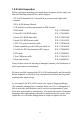
LVDS connector, dual channel: 25 MHz to 112 MHz DVI connector: 2048 x 1536, 75 MHz 1.3.5 Ethernet LAN • Supports single 10/100Base-T networking or single/dual10/100/ 1000Base-T Ethernet networking • Controller: • Single 10/100Base-T: Intel 82551QM • Single 10/100/1000Base-T: Intel 82541GI(PCI) • Dual 10/100/1000Base-T: Two Intel 82541GI (PCI) 1.3.6 Ultra 160 SCSI • Provides dual channel Ultra 160 SCSI interface • Chipset: Adaptec AIC7899 1.3.
ers. Chapter 2 gives instructions for connecting external devices to your single board computer. Table 1.1: Jumpers Label Function J1 CMOS Clear J2 Watchdog timer output selection Table 1.
Table 1.
1.5 Board Layout: Jumper and Connector Location Figure 1.
Figure 1.2: I/O Connectors 68 Pin for Ultra 160 50 Pin for Ultra wide SCSI Adaptec AIC-7899 68 Pin for Ultra 160 Figure 1.
1.6 PCA-6189 Block Diagram Figure 1.
1.7 Safety Precautions Warning! Always completely disconnect the power cord from your chassis whenever you work with the hardware. Do not make connections while the power is on. Sensitive electronic components can be damaged by sudden power surges. Only experienced electronics personnel should open the PC chassis. Caution! Always ground yourself to remove any static charge before touching the single board computer. Modern electronic devices are very sensitive to static electric charges.
1.8 Jumper Settings This section provides instructions on how to configure your single board computer by setting the jumpers. It also includes the single board computer's default settings and your options for each jumper. 1.8.1 How to set jumpers You can configure your single board computer to match the needs of your application by setting the jumpers. A jumper is a metal bridge that closes an electrical circuit.
Table 1.6: Watchdog timer output (J2) Function Jumper Setting IRQ11 1 1-2 closed * Reset 1 2-3 closed * default setting Note: The interrupt output of the watchdog timer is a low level signal. It will be held low until the watchdog timer is reset. 1.9 System Memory The PCA-6189 has two sockets for 184-pin dual inline memory modules (DIMMs). All these sockets use 2.5 V unbuffered double data rate synchronous DRAMs (DDR SDRAM). They are available in capacities of 128, 256, 512 and 1024 MB.
1.9.1 CPU FSB and memory speed The PCA-6189 can accept DDR SDRAM memory chips without parity. Also note: The PCA-6189 accepts PC2100 (DDR266), PC2700 (DDR 333) and DDR SDRAM, depending on the CPU front side bus frequency (FSB). Please refer to the table below for the relationship between the CPU FSB and memory speed. Table 1.
Warning: Without a fan or heat sink, the CPU will over-heat and cause damage to both the CPU and the single board computer. To install a CPU, first turn off your system and remove its cover. Locate the processor socket 479. 1. To open the socket, turn the socket screw clockwise as far as it will go. 2. Place the CPU in the empty socket and then follow the instructions that came with the CPU.
PCA-6189 User’s Manual 16
CHAPTER 2 Connecting Peripherals 17 Chapter 2
Chapter 2 Connecting Peripherals 2.1 Introduction You can access most of the connectors from the top of the board while it is installed in the chassis. If you have a number of cards installed or have a packed chassis, you may need to partially remove the card to make all the connections. 2.2 1st & 2nd (CN1, CN2) IDE Connectors CN1 CN2 You can attach up to four IDE (Integrated Drive Electronics) drives to the PCA-6189’s built-in controller.
Connect the first hard drive to the other end of the cable. Wire 1 on the cable should also connect to pin 1 on the hard drive connector, which is labeled on the drive circuit board. Check the documentation that came with the drive for more information. Connect the second hard drive to the remaining connector (CN2 or CN1), in the same way as described above. 2.3 Floppy Drive Connector (CN3) CN3 You can attach up to two floppy disk drives to the PCA-6189's on board controller. You can use 3.5" (720 KB, 1.
2.4 Parallel Port (CN4) CN4 The parallel port is normally used to connect the single board computer to a printer. The PCA-6189 includes an onboard parallel port, accessed through a 26-pin flat-cable connector, CN4. The card comes with an adapter cable which lets you use a traditional DB-25 connector. The cable has a 26-pin connector on one end and a DB-25 connector on the other, mounted on a retaining bracket.
2.5 USB Ports CN6, CN31, and CN32 CN6 The PCA-6189 provides up to four ports for the USB (Universal Serial Bus) interface, which gives complete Plug & Play and hot swapping for up to 127 external devices.The USB interface complies with USB Specification Rev. 2.0, supports transmission rate up to 480 Mbps and is fuseprotected. The USB interface can be disabled in the system BIOS setup. Connector CN31 connects to USB ports 0 and 1, while CN6 and CN32 share ports 2 and 3.
2.6 VGA Connector CN7 CN7 The PCA-6189 includes a VGA interface that can drive conventional CRT displays. CN7 is a standard 15-pin D-SUB connector commonly used for VGA. Pin assignments for CRT connector CN7 are detailed in Appendix B. 2.7 LVDS connector VCN2 The PCA-6189 provides a LVDS interface that supports 18-bit LCD panels. Pin assignments for the LVDS connector VCN2 are detailed in Appendix B.
2.8 DVI connector VCN3 The VCN3 provides a DVI interface that supports DVI display. This connector should be used with a 20-pin DVI cable (p/n: 1700000821) Pin assignments for the VCN3 are detailed in Appendix B. 2.9 Ethernet Connector (CN8 and CN34) The PCA-6189 is equipped with single/dual high-performance 32-bit PCI-bus Ethernet interface, which is fully compliant with IEEE 802.3/u 10/100Mbps CSMA/CD and IEEE 802.3ab 1000Base-T standards.
2.10 Serial Ports (COM1 : CN9; COM2 : CN10 ) The PCA-6189 offers two serial ports, CN9 as COM1 and CN10 as COM2. These ports can connect to serial devices, such as a mouse or a printer, or to a communications network. The IRQ and address ranges for both ports are fixed. However, if you want to disable the port or change these parameters later, you can do this in the system BIOS setup. Different devices implement the RS-232 standard in different ways.
2.12 External Keyboard Connector (CN12) CN12 In addition to the PS/2 mouse/keyboard connector on the PCA-6189's rear plate, there is also an extra onboard external keyboard connector. This gives system integrators greater flexibility in designing their systems. 2.13 CPU Fan Connector (CN14) CN14 If fan is used, this connector supports cooling fans of 500mA (6W) or less.
2.14 Front Panel Connectors (CN16, 17, 18, 19, 21&29) There are several external switches to monitor and control the PCA-6189 CN21 CN19 CN17 CN16 CN18 CN29 2.14.1 Power LED (CN16) CN16 is a 5-pin connector for the power on LED. Refer to Appendix B for detailed information on the pin assignments. If a PS/2 or ATX power supply is used, the system's power LED status will be as indicated below: Table 2.
2.14.3 Reset (CN18) Many computer cases offer the convenience of a reset button. Connect the wire from the reset button. 1 2.14.4 HDD LED (CN19) You can connect an LED to connector CN19 to indicate when the HDD is active. 1 2.14.5 ATX soft power switch (CN21) If your computer case is equipped with an ATX power supply, you should connect the power on/off button on your computer case to CN21. This connection enables you to turn your computer on and off. 2.14.
2.15 ATX feature connector (CN20) CN20 Connect to the CN1 on the Advantech backplane to enable the ATX function, 5V stand-by. 2.16 AC-97 Audio interface (CN43) CN43 The PCA-6189 provides AC-97 audio through PCA-AUDIO-00A1 module from Advantech.
2.17 Serial ATA interface (SA0 and SA1) SA0 & SA1 In addition to the two EIDE interfaces (up to four devices), the PCA-6189 features high performance serial ATA interface (up to 150MB/s) which eases cabling to hard drives with thin and long cables. 2.18 Connecting to SNMP-1000 remote manager Use the 6-pin to 8-pin cable to connect the single board computer to SNMP-1000. This cable comes with the SNMP-1000.
2.19 Auxiliary 4-pin power connector (ATX1) To ensure the sufficiency of power supply for Pentium M or Celeron M single board computer, one auxiliary 4 pin power connector is available on PCA-6189. This connector must be connected to the power supply, otherwise system might be unstable.
CHAPTER 3 Award BIOS Setup 31 Chapter 3
Chapter 3 Award BIOS Setup 3.1 Introduction Award’s BIOS ROM has a built-in setup program that allows you to modify the basic system configuration. This type of information is stored in battery-backed memory (CMOS RAM) so that it retains the setup information when the power is turned off. 3.1.1 CMOS RAM Auto-backup and Restore The CMOS RAM is powered by an onboard button cell battery. When you finish BIOS setup, the data in CMOS RAM will be automatically backed up to Flash ROM.
3.2 Entering Setup Turn on the computer and press to enter the BIOS setup. Figure 3.1: Award BIOS Setup initial screen 3.3 Standard CMOS Setup Choose the Standard CMOS Features option from the initial setup screen menu to display the screen below. This menu allows you to configure system components such as date, time, hard disk drive, floppy drive, display, and memory. Figure 3.
3.4 Advanced BIOS Features The Advanced BIOS Features screen appears when you choose the Advanced BIOS Features item from the initial setup screen menu. Use this screen to configure the PCA-6189 according to your particular requirements. Below are some major items that are provided in the Advanced BIOS Features screen. A quick booting function is provided for your convenience. Simply enable the Quick Booting item to save yourself valuable time. Figure 3.3: Advanced BIOS features screen 3.4.
3.4.5 Quick Power On Self Test This setting allows the system to skip certain tests while booting. This will decrease the time needed to boot the system. 3.4.6 First/Second/Third Boot Device The BIOS will load the OS with the devices in the sequence selected. The sequence includes: Floppy, LS120, HDD-0, SCSI, CDROM, HDD-1, HDD-2, HDD-3, ZIP100, USB-FDD, USB-ZIP, USBCDROM, USBHDD, LAN, and Disabled. 3.4.7 Boot Other Device Use this option to choose another device to boot.
3.4.15 Security Option Choose an option for this setting to have the system prompt for a password every time the system boots or only when you enter setup. System: The system will not boot and access to setup will be denied if the correct password is not entered at the prompt. Setup: The system will boot, but access to Setup will be denied if the correct password is not entered at the prompt. Note: To disable security, select “PASSWORD SETTING” in the main menu.
3.5 Advanced Chipset Features By choosing the Advanced Chipset Features option from the Initial Setup Screen menu, the screen below will be displayed. This sample screen contains the manufacturer’s default values for the PCA-6189, as shown in Figure 3-4: Note: DRAM default timings have been carefully chosen and should ONLY be changed if data is being lost. Please first contact technical support. Figure 3.4: Advanced chipset features screen 3.5.
3.5.4 DRAM RAS# to CAS# Delay In order to improve performance, certain space in memory is reserved for ISA cards. This memory must be mapped into the memory space below 16 MB. The choices are: 3 and 2. 3.5.5 DRAM RAS# Precharge This controls the idle clocks after issuing a precharge command to DRAM. You can leave this on the default setting. The choices are: 3 and 2. 3.5.6 DRAM Data Integrity Mode System can auto-detect the SDRAM module whether the module supports ECC or not.
3.5.12 AGP Aperture Size (MB) Use this setting to select the size of the Accelerated Graphics Port (AGP) aperture. The aperture is a portion of the PCI memory address range dedicated to graphics memory address space. Host cycles that hit the aperture range are forwarded to the AGP without any translation. The choices are: 64, 128, and 256. 3.5.13 Init Display First Choose the first display interface to initiate while booting. The choices are PCI Slot and Onboard/AGP. 3.5.
3.6 Integrated Peripherals Figure 3.5: Integrated peripherals 3.7 On-chip IDE Device Figure 3.6: On-Chip IDE Device 3.7.1 IDE DMA transfer access This setting controls the DMA function of hard disk drive. The choices are Enabled or Disabled. Choose Enabled to assign the IDE DMA function.
3.7.2 On-Chip IDE Device IDE Primary (Secondary) Master/Slave PIO/UDMA Mode (Auto) Each channel (Primary and Secondary) has both a master and a slave, making four IDE devices possible. Because each IDE device may have a different Mode timing (0, 1, 2, 3, 4), it is necessary for these to be independent. The default setting Auto will allow auto-detection to ensure optimal performance. 3.7.3 On-Chip Serial ATA Choose the status of serial ATA.
3.8.1 USB Controller Select Enabled if your system contains a Universal Serial Bus (USB) controller and you have USB peripherals. The choices are Enabled or Disabled. 3.8.2 USB 2.0 Controller Use this option to disable/enable the USB 2.0 controller only. The BIOS itself may/may not have high speed USB support. If the BIOS has high speed USB support built in, the support will turn on automatically when a high speed device is attached. The choices are Enabled or Disabled. 3.8.
3.9.1 On-board FDC Controller When enabled, this field allows you to connect your floppy disk drives to the onboard floppy disk drive connector instead of a separate controller card. If you want to use a different controller card to connect the floppy disk drives, set this field to Disabled. 3.9.2 On-board Serial Port 1 The settings are 3F8/IRQ4, 2F8/IRQ3, 3E8/IRQ4, 2E8/ IRQ3, Auto, and Disabled for the on-board serial connector. 3.9.
faster than the maximum data transfer rate. ECP+EPP allows normal speed operation in a two-way mode. 3.9.11 EPP Mode Select This field allows you to select EPP port type 1.7 or 1.9. The choices are: EPP1.9 or EPP1.7. 3.9.12 ECP Mode Use DMA This selection is available only if you select “ECP” or “ECP + EPP” in the Parallel Port Mode field. In ECP Mode Use DMA, you can select DMA channel 1, or DMA channel 3. Leave this field on the default setting. 3.9.
Max Saving, the values for HDD Power Down and Suspend Mode (the following settings) are filled in automatically. If you select User Defined, you must also enter values for HDD Power Down and Suspend Mode. Table 3.1: Power Management settings Min Saving For minimum power usage, sets Suspend Mode to 1 hour and set HDD Power Down to 15 minutes.
3.10.9 Power On by LAN Choose Enabled to resume system function by LAN, or choose Disabled to resume system function by PCI card. 3.10.10 Power On by Modem This item allows you to wake up the system via a COM port from the remote host. The choices are Enabled and Disabled. 3.10.11 Power On by Alarm The choices are Enabled and Disabled. 3.10.12 Primary IDE (0,1) and Secondary IDE (0,1) Choose Enabled to set the system to resume from suspend mode when Primary IDE (0,1) or Secondary IDE (0,1) is active.
3.11.1 PNP OS Installed Set this option to Yes if PNP OS is installed on your system. The default value for this setting is No. 3.11.2 Reset Configuration Data Default is Disabled. Select Enable to reset Extended System Configuration Data (ESCD) if you have installed a new add-on and system configuration has caused such a conflict that the OS cannot boot. 3.11.3 Resources Controlled By The values for this option are Auto (ESCD) and Manual.
3.12.2 Current System Temp This shows you the current temperature of system. 3.12.3 Current CPU Temperature This shows you the current CPU temperature. 3.12.4 Current CPUFAN Speed This shows you the current CPU fan operating speed. 3.12.5 VCORE, VBAT(V), 5VSB(V) This shows you the voltage of VCORE, +1.5 V, 3.3 V, +5 V, +12 V, -12 V, -5 V, VBAT(V), and 5VSB(V). 3.12.6 Shutdown Temperature This option sets the temperature at which the system will shut down if the CPU overheats.
3.14 Passwords and Settings 3.14.1 Load Setup Defaults Choose the Load Setup Defaults selection from the initial setup screen. At the prompt, enter Y to return system setup options to default values. 3.14.2 Set Supervisor Password Choose the Set Supervisor Password selection from the initial setup screen. At the ENTER PASSWORD: prompt, enter a password with up to eight characters. Typing a password clears any previously entered password form CMOS memory.
PCA-6189 User’s Manual 50
CHAPTER 4 Chipset Software Installation Utility 51 Chapter 4
Chapter 4 Chipset Software Install Utility 4.1 Before you begin To facilitate the installation of the enhanced display device drivers and utility software, you should read the instructions in this chapter carefully before you attempt installation. The device drivers for the PCA-6189 board are located on the software installation CD. The auto-run function of the driver CD will guide and link you to the utilities and device drivers under a Windows system.
• Identification of Intel chipset components in the Device Manager. • Integrates superior video features. These include filtered sealing of 720 pixel DVD content, and MPEG-2 motion compensation for software DVD Note: This utility is used for the following versions of Windows system, and it has to be installed before installing all the other drivers: Windows 98SE Windows 2000, Windows ME, Windows XP 4.3 Windows XP Driver Setup 1. Insert the driver CD into your system's CD-ROM drive.
2. Click "Next" when you see the following message. 3. Click "Yes" when you see the following message.
4. Click "Next" when you see the following message. 5. When the following message appears, click "Finish" to complete the installation and restart Windows.
PCA-6189 User’s Manual 56
CHAPTER 5 VGA Setup 57 Chapter 5
Chapter 5 VGA Setup 5.1 Introduction The PCA-6189 has VGA onboard, you need to install the VGA driver to enable the function. The Intel 855GME Chipset provides a highly integrated graphics accelerator delivering high performance 2D, 3D, and video capabilities. With its interfaces to UMA using a DVMT configuration, an analog display, a LVDS port, and two digital display ports (e.g. flat panel), the GMCH can provide a complete graphics solution.
5.3 Windows XP Driver Setup Note: Before installing this driver, make sure the CSI utility has been installed in your system. See Chapter 4 for information on installing the CSI utility 1. Insert the driver CD into your system's CD-ROM drive. In a few seconds, the software installation main menu appears, as shown in the following figure. Under the "VGA DRIVERS" heading, click on one of the buttons (labeled "W2K XP" and "WIN NT" respectively) according to the operating system you are using.
2. You will see a welcome window. Please chick on "Next" to continue the installation.
3. Click "Yes" when you see the following message. 4.
5. Click "Finish" to complete the installation and restart the computer now or later.
CHAPTER 6 LAN Configuration 63 Chapter 6
Chapter 6 LAN Configuration 6.1 Introduction The PCA-6189 features the 32-bit 10/100/1000 Mbps Ethernet network interface. This interface supports bus mastering architecture and autonegotiation features. Therefore standard twisted-pair cabling with RJ-45 connectors for 10 Mbps, 100 Mbps and 1000 Mbps connections can be used. Extensive driver support for commonly-used network systems is also provided. 6.
6.3 Installation Note: Before installing the LAN drivers, make sure the CSI utility has been installed in your system. See Chapter 4 for information on installing the CSI utility. The PCA-6189's onboard Ethernet interface supports all major network operating systems. However, the installation procedure varies with different operating systems. In the following sections, refer to the one that provides driver setup procedure for the operating system you are using. 6.
2. Select "I accept the terms in the license agreement" and click "Next" to continue. 3. Click "Next" to continue.
4. Click "Install Software" to start the installation procedure. 5.
PCA-6189 User’s Manual 68
CHAPTER 7 SCSI Setup & Configuration 69 Chapter 7
Chapter 7 SCSI Setup & Configuration 7.1 Introduction The PCA-6189 is equipped with an Adaptec AIC-7899 single-chip PCIto-SCSI host adapter which provides a dual channel Ultra 160 multitasking interface between your computer.s PCI bus and SCSI devices (disk drives, CD-ROM drives, scanners, tape backups, removable media drives, etc.). Ultra 160 is a new generation of SCSI technology that expands SCSI performance from 80 MBytes/sec to 160 MBytes/ sec.
7.2 Understanding SCSI SCSI (pronounced .scuzzy.) stands for Small Computer Systems Interface. SCSI is an industry standard computer interface for connecting SCSI devices to a common SCSI bus. A SCSI bus is an electrical pathway that consists of a SCSI interface installed in a computer and one or more SCSI devices. SCSI cables are used to connect the devices to the SCSI interface.
• If you are booting your computer from a SCSI hard disk drive connected to the SCSI bus, the Boot SCSI ID setting in the SCSISelect utility must correspond to the SCSI ID of the device from which you are booting. By default, the Boot SCSI ID is set to 0. We recommend that you do not change this setting. • In Windows 95/98, you can use the Device Manager to determine which SCSI ID is assigned to each installed SCSI device. 7.
7.5 Configuring the SCSI interface with SCSISelect SCSISelect, included with the CPU card, enables you to change SCSI settings without opening the computer. SCSISelect also enables you to lowlevel format or verify the disk media of your SCSI hard disk drives. The following table lists the available and default settings for each SCSISelect option. Note: The default settings are appropriate for most systems.
SCSI Device Configuration: Sync Transfer Rate (MBytes/sec) 160, 80.0, 53.4, 40.0, 160 32.0, 26.8, 20.0, 16.0, 13.4, 10.
BIOS Support for Bootable CD_ROM2 Enabled, Disabled Enabled BIOS Support for Int 13 Enabled, Disabled Enabled Extensions2 1 Setting is valid only if Multiple LUN Support is enabled. 2 Settings are valid only if host adapter BIOS is enabled. 7.6 Starting SCSISelect Follow these steps to start SCSISelect: 1. Turn on or restart your system. During the startup process, pay careful attention to the messages that appear on your screen. 2.
Using SCSISelect Settings To select an option, use the arrow keys to move the cursor to the option, then press ENTER. In some cases, selecting an option displays another menu. You can return to the previous menu at any time by pressing ESC. To restore the original SCSISelect default values, press F6 from the main SCSISelect screen. SCSI Bus Interface Definitions • Host Adapter SCSI ID-(Default: 7) Sets the SCSI ID for the SCSI controller.
• Initiate Wide Negotiation-(Default: Yes) When set to Yes, the SCSI card attempts 16-bit data transfer (wide negotiation.) When set to No, the SCSI card uses 8-bit data transfer unless the SCSI device requests wide negotiation. Note: Set Initiate Wide Negotiation to NO if you are using an 8-bit SCSI device that hangs or exhibits other performance problems with 16-bit data transfer rate enabled. • Enable Disconnection-(Default: Yes) When set to Yes, allows the SCSI device to disconnect from the SCSI bus.
• Display Messages during BIOS Initialization-(Default: Enabled) When set to Enabled, the SCSI card BIOS displays the Press for SCSI Select (TM) Utility! message on your screen during system bootup. If this setting disabled, you can still invoke the SCSISelect Utility by pressing after the SCSI card BIOS banner appears.
• Support Removable Disks Under BIOS as Fixed Disks. (Default: Disabled) Determines which removable-media drives are supported by the SCSI card BIOS. Choices are as follows: • Disabled. No removable-media drives are treated as hard disk drives. Software drivers are required because the drives are not controlled by the BIOS. • Boot Only.Only the removable-media drive designated as the boot device is treated as a hard disk drive. • All Disks.
7.8 Installation under Windows 2000 If you are only using SCSI hard drives without any IDE HDD drive installed. Please follow these steps: 1. Insert Windows 2000 CD Disk. 2. Press F6 immediately when it displays: “Set up is inspecting your computer’s hardware configuration.” 3. Then it enter SCSI installation. Please insert SCSI driver floppy disk. 7.9 Windows 9X Driver setup procedure 1. In the window 9x screen, click on “start” and select “setting”.
2. In the “System properties”, choose “PCI SCSI Bus Controller.” Then click on “Properties.” 3.
4. Click on “Next” 5.
6. If the SCSI driver is supplied in floppy disk, click on “Floppy disk drives.” Then, click on “Next.” If the SCSI driver is supplied in CD-ROM disk, click on “Specify a location:" then enter "E:\Drv_SCSI\AIC7899\Windows\Win9X" 7. In the "Update Device Driver Wizard" click on "Next.
8. The installation is completed. Click on "Finish." 9. Click on "Yes" to restart the system.
CHAPTER 8 USB 2.
Chapter 8 USB 2.0 Configuration 8.1 Introduction The PCA-6189 is designed with Intel 6300ESB which supports both USB 1.1 and USB 2.0 high-speed transmission. It still remains the compatibility with today's USB device. High-speed USB 2.0 provides data transfer up to 480Mb/s which is 40 times faster than USB 1.1. It is ideal for today's speed-demanding I/O peripherals. 8.2 Features • Provides data transmission rate up to 480Mb/s • Offer 40 greater bandwidth than USB 1.
CHAPTER 9 Onboard Security Setup 87 Chapter 9
Chapter 9 Onboard Security Setup 9.1 Introduction The PCA-6189's hardware monitor is designed with Winbond W83627HF. Onboard security (OBS) functions monitor key hardware. They help you maintain your system's stability and durability. The PCA-6189 can monitor 5 sets of system positive voltages, 2 sets of system negative voltages, CPU cooling fan speed, and CPU temperature. The positive system voltage sets which can be monitored include: • CPU core voltage: 1.3 V ~ 3.3 V, according to Intel specifications.
9.2 Windows XP Driver Setup 1. Insert the driver CD into your system's CD-ROM drive. In a few seconds, the software installation main menu appears, as shown in the following figure. Click on the "Install" button under the "OBS DRIVERS" heading. 2. Click "Next" when you see the following message.
3. Click "Next" when you see the following message. 4. Click "Next" when you see the following message. 5. Click "Next" to continue.
6. Click "Finish" when you see the following message. 9.3 Using the OBS Hardware Doctor Utility After completing the setup, all the OBS functions are permanently enabled. When a monitored reading exceeds safe limits, a warning message will be displayed and an error beep tone will activate to attract your attention. OBS Hardware Doctor will show an icon on the right side of the bottom window bar. This icon is the "Terminate and Stay Resident" (TSR) icon.
2. It is recommended that you load the default values for all the OBS settings. However, if desired, you can establish new conditions for voltage, fan speed, and temperature.
CHAPTER 10 SATA RAID Setup 93 Chapter 10
Chapter 10 SATA RAID Setup 10.1 Introduction To support demanding disk I/O, Intel 6300ESB chipset integrates two Serial ATA controllers with software RAID 0 and 1 capability. RAID 0 stripping increases the storage performance and is designed to speed up data transfer rates for disk-intensive applications. RAID 1 mirroring protects valuable data that might be lost in the event of a hard drive failure.
10.3 Array Configuration Utility Select the “Array Configuration Utility” in the “Initial Setup Screen” menu, and the “SATA RAID Setup Main Menu screen” screen will display. This menu allows users to configure RAID function such as manage/create array, add/delete hotspare and initialize drives. Figure 10.2: SATA RAID Setup Main Menu screen 10.3.1 Managing Arrays Viewing Array Properties 1. From the manual, select the “Manage Arrays” 2.
10.3.2 Creating Arrays Before creating arrays, please make sure that the disks for the array already connected and installed in the system. 1. Select “Create Array” from the setup main menu 2. Select the disks for the new array then press “Insert”. To deselect any disk, highlight the disk then press “Delete” 3. Press “Enter” when both selected disks ready, then the Array Properties menu displays 4. In the Array Properties menu, select a type of array and press “Enter”. 5.
4. Press “Enter” 5. Read the warning message and type “Y” to continue 10.3.6 Rebuilding Arrays You can rebuild the array to have optimal status by replacing a failed disk of a RAID 1 or RAID 10 array with a new disk. Note: Rebuilding applies to Fault Tolerant arrays (RAID 1) only. You can perform a Rebuild in the following ways: System Shutdown Rebuild Shutdown the system and replace the failed disk with a new one with equal or greater capacity.
3. When the array is build, insert the driver CD and restart the system 4. Windows searches the disk for a suitable driver 5. When the Adaptec Embedded Serial ATA HostRAID driver is found, press “Enter”. Follow the instructions to complete your installation.
Appendix A Programming the Watchdog Timer 99 Appendix A
Appendix A Programming the watchdog A.1 Programming the Watchdog Timer The PCA-6189's watchdog timer can be used to monitor system software operation and take corrective action if the software fails to function after the programmed period. This section describes the operation of the watchdog timer and how to program it. A.1.1 Watchdog timer overview The watchdog timer is built-in the super I/O controller W83627HF.
Unlock W83627H Select register of watchdog timer Enable the function of the watchdog timer Use the function of the watchdog timer Lock W83627HF 101 Appendix A
Watchdog Timer Registers Address of register (2E) Attribute Read/Write Value (2F) and description 87 (hex) ----- Write this address to I/O address port 2E (hex) twice to unlock theW83627HF 07 (hex) write Write 08 (hex) to select register of watchdog timer. 30 (hex) write Write 01 (hex) to enable the function of the watchdog timer. Disabled is set as default. F5 (hex) write Set seconds or minutes as units for the timer.
F7 (hex) read/write Bit 6: Write 1 to enable keyboard to reset the timer, 0 to disable.[default] Bit 5: Write 1 to generate a timeout signal immediately and automatically return to 0. [default=0] Bit 4: Read status of watchdog timer, 1 means timer is ""time out""." AA (hex) ----- Write this address to I/O port 2E (hex) to lock the watchdog timer.2 Table A.1: Watchdog timer registers A.1.4 Example Program 1. Enable watchdog timer and set 10 sec.
;----------------------------------------------------------Dec dx ; Set second as counting unit Mov al,0f5h Out dx,al Inc dx In al,dx And al,not 08h Out dx,al ;----------------------------------------------------------Dec dx ; Set timeout interval as 10 seconds and start counting Mov al,0f6h Out dx,al Inc dx Mov al,10 Out dx,al ;----------------------------------------------------------Dec dx ; lock W83627HF Mov al,0aah Out dx,al 2.
;----------------------------------------------------------Dec dx ; Enable the function of watchdog timer Mov al,30h Out dx,al Inc dx Mov al,01h Out dx,al ;----------------------------------------------------------Dec dx ; Set minute as counting unit Mov al,0f5h Out dx,al Inc dx In al,dx Or al,08h Out dx,al ;----------------------------------------------------------Dec dx ; Set timeout interval as 5 minutes and start counting Mov al,0f6h Out dx,al Inc dx Mov al,5 Out dx,al ;-------------------
Out dx,al ;----------------------------------------------------------Mov al,07h ; Select registers of watchdog timer Out dx,al Inc dx Mov al,08h Out dx,al ;----------------------------------------------------------Dec dx ; Enable the function of watchdog timer Mov al,30h Out dx,al Inc dx Mov al,01h Out dx,al ;----------------------------------------------------------Dec dx ; Enable watchdog timer to be reset by mouse Mov al,0f7h Out dx,al Inc dx In al,dx Or al,80h Out dx,al ;------------------
Out dx,al ;----------------------------------------------------------Mov al,07h ; Select registers of watchdog timer Out dx,al Inc dx Mov al,08h Out dx,al ;----------------------------------------------------------Dec dx ; Enable the function of watchdog timer Mov al,30h Out dx,al Inc dx Mov al,01h Out dx,al ;----------------------------------------------------------Dec dx ; Enable watchdog timer to be strobed reset by keyboard Mov al,0f7h Out dx,al Inc dx In al,dx Or al,40h Out dx,al ;-------
Out dx,al ;----------------------------------------------------------Mov al,07h ; Select registers of watchdog timer Out dx,al Inc dx Mov al,08h Out dx,al ;----------------------------------------------------------Dec dx ; Enable the function of watchdog timer Mov al,30h Out dx,al Inc dx Mov al,01h Out dx,al ;----------------------------------------------------------Dec dx ; Generate a time-out signal Mov al,0f7h Out dx,al Inc dx In al,dx ;Write 1 to bit 5 of F7 register Or al,20h Out dx,al ;
Appendix B I/O Pin Assignments 109 Appendix B
Appendix B Pin Assignments B.1 IDE Hard Drive Connector (CN1, CN2) Table B.
B.2 Floppy Drive Connector (CN3) 33 31 3 1 34 32 4 2 Table B.
B.3 Parallel Port Connector (CN4) 13 12 2 1 26 25 15 14 Table B.
B.4 USB Connector (CN6) 1 2 3 4 5 6 7 8 9 10 Table B.4: USB1/USB2 connector (CN6) Pin USB1 Signal Pin 1 +5 V 6 2 UV7 3 UV+ 8 4 GND 9 5 Chassis GND 10 USB2 Signal +5 V UVUV+ GND N/CA B.5 VGA Connector (CN7) 5 1 10 6 15 11 Table B.
B.6 VCN2 LVD connector (Insert diagram) Table B.
B.7 VCN3 DVI connector (insert diagram) Table B.7: VCN3 DVI connector Pin Signal Pin 1 #TMDS1_0 11 2 AGP_5V_TMDS2 12 3 TMDS1_0 13 4 GND 14 5 GND 15 6 TMDS1_CK 16 7 #TMDS1_1 17 8 GND 18 9 #TMDS1_1 19 10 DDC3_SCLOUT 20 Signal GND DDC3_SDAOUT #TMDS1_2 #TMDS1_2 TMDS1_2 ATI_12C_DAT AGP_5V_TMDS2 ATI_12C_CLK CPIS_ENA_BL CPIS_VDD_VCL B.8 COM1/COM2 RS-232 Serial Port (CN9, CN10) (insert diagram) Table B.
B.9 PS/2 Keyboard/Mouse Connector (CN11) (INSERT DIAGRAM) Table B.9: PS/2 keyboard/mouse connector (CN11) Pin Signal 1 KB DATA 2 MS DATA 3 GND 4 VCC 5 KB CLOCK 6 MS CLOCK B.10 External Keyboard Connector (CN12) (Insert diagram) Table B.10: External keyboard connector (CN12) Pin Signal 1 CLK 2 DATA 3 NC 4 GND 5 VCC B.11 Power LED (CN16) (insert diagram) Table B.
B.12 Power LED (CN16) (insert diagram) Table B.12: Power LED (CN16) Pin 1 2 3 4 5 Function LED power (+5 V) NC GND NC GND B.13 External Speaker Connector (CN17) (insert diagram) Table B.
B.14 Reset Connector (CN18) 1 Table B.14: Reset connector (CN18) Pin Signal 1 RESET 2 GND B.15 ATX Feature Connector (CN20) 1 Table B.
B.16 ATX Feature Connector (CN20) 1 Table B.16: ATX Feature Connector (CN20) Pin Signal 1 PS-ON 2 VCC 3 VCCSB B.17 ATX Soft Power Switch (CN21) 1 Table B.
B.18 H/W Monitor Alarm (CN22) 1 Table B.18: H/W Monitor alarm (CN22) Pin Signal 1 Enable OBS alarm 2 Disable OBS alarm B.19 SM Bus Connector (CN29) 1 Table B.
B.20 Audio Interface (CN43) (insert diagram) Table B.20: Audio Interface(CN 43) 1 VCC 2 GND 3 Sync 5 SDOUT 7 SDIN1 9 +12V 11 GND 4 BITCLK 6 SDIN0 8 AC-RST 10 GND 12 N/C B.21 LCD Inverter power connectore (VP1) (insert diagram) Table B.
B.22 System I/O Ports Table B.22: System I/O ports Addr.
B.23 DMA Channel Assignments Table B.23: DMA channel assignments Channel Function 0 Available 1 Available 2 Floppy disk (8-bit transfer) 3 Available 4 Cascade for DMA controller 1 5 Available 6 Available 7 Available B.24 Interrupt Assignments Table B.
B.25 1st MB Memory Map Table B.25: 1st MB memory map Addr. range (Hex) E0000h - FFFFFh CC000h - DFFFFh C0000h - CBFFFh A0000h - BFFFFh 00000h - 9FFFFh Device BIOS Unused VGA BIOS Video Memory Base memory B.26 PCI Bus Map Table B.