Service Manual SRP-275 Impact Printer Rev. 2.00 http://www.samsungminiprinters.
SRP-275 ■ Table of Contents 1. Precaution Segment ................................................................................................................................ 6 1-1 Safety Precautions............................................................................................................................... 6 1-2 Servicing Precaution............................................................................................................................
SRP-275 4. Hardware ................................................................................................................................................ 48 4-1 Wiring Diagram .................................................................................................................................. 48 4-1-1 Main board wiring diagram.......................................................................................................... 48 4-1-2 Connector sub PCB wiring diagram............
SRP-275 5-4 SRP-275 Whole unit Sub-assembly .................................................................................................. 97 5-4-1 Cover base assy ......................................................................................................................... 97 5-4-2 Switch-paper near end assy ....................................................................................................... 98 5-4-3 Switch-paper end assy....................................................
SRP-275 ■ About About this Manual This Service Manual describes how to perform hardware service maintenance for the BIXOLON SRP-275 Impact Printer. Notes Notes may appear anywhere in the manual. They draw your attention to additional information about the item. Precaution symbols NOTICE Indicates a Safety Precaution that applies to this part component. CAUTION Use caution when handling these parts. Copyright ⓒ 2005 by BIXOLON Co., Ltd. All right reserved.
SRP-275 1. Precaution Segment Follow these safety, servicing and ESD precautions to prevent damage and to protect against potential hazards such as electrical shock. 1-1 Safety Precautions 1. Be sure that all built-in protective devices are in place. Restore any missing protective shields. 2. When re-installing chassis and assemblies, be sure to restore all protective devices, including control knobs and compartment covers. 3.
SRP-275 1-2 Servicing Precaution WARNING 1 : First read the “Safety Precautions” section of this manual. If some unforeseen circumstance creates a conflict between the servicing and safety precautions, always follow the safety precautions. WARNING 2 : An electrolytic capacitor installed with the wrong polarity might explode. 1.
SRP-275 1-4 Introduction The SRP-275 is a high-quality impact dot matrix POS printer. This one-station printer has the following features. • Compact design and light-weight. • High-speed printing using logic-seeking. • Easy to use : Easy paper loading. • High reliability and long life due to the use of stepping motors for head carriage return and paper feeding. • Two color printing (red/black) available. • Various formats are possible because the paper feeding pitch is selectable.
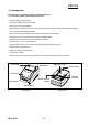
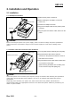
SRP-275 2. Installation and Operation 2-1 Installation 2-1-1 AC Adapter Installation 1) Make sure the printer is turned off. AC adaptor 2) Before inserting the AC adaptor, connect the Power connector power cord. 3) Insert the AC adaptor as shown. 4) Plug the AC adapter cable into the printer’s power connector. Power cord 5) Plug the power cord into the outlet, and turn on the power.
SRP-275 2-1-3 Ribbon Cartridge Installation 1) Before inserting the ribbon cassette, turn the knob clockwise to prevent twisting the ribbon. 2) Open the front cover of printer. 3) Take out the old ribbon cassette if there is one. 4) Insert the new ribbon cassette as shown and pay particular attention to the placement of the ribbon in front of the Printer Head. 5) During inserting the ribbon cassette, turn the knob clockwise again to make sure the ribbon moves freely in the cassette.
SRP-275 2-1-4 Paper Roll Installation 1) To prevent data loss, make sure that the printer is not receiving data. 2) Open the rear cover by pushing the open button and push the arrow mark back. 3) Remove the used paper roll core if there is one. 4) Insert the paper roll as shown. 5) Be sure to note the correct direction that the paper should come off the paper roll. 6) Pull out small amount of paper as shown.
SRP-275 2-1-5 Changing the paper width Screw(3x6)(2pieces) 1) Open the rear cover. Frame paper control 2) Remove the Frame paper control by loosing the two screws(3×6). 3) Reattach the Frame paper control in your wanting position. (Insert and tighten two screws(3×6) to reattach.) 4) Close the rear cover. 57.5mm 69.5mm 76mm(default) 5) Change the Memory Switch setting for changing paper roll width. (See the instructions "Setting the Memory Switches" in 2-2.Operation) Rev. 2.
SRP-275 2-1-6 Wall Mount Installation Bracket hanger 1) Turn the Set over and attach the Bracket hanger to the Frame base then tighten four screws. Screw(3x5) (4pieces) Bracket mount 2) Attach the Bracket mount to the wall firmly with the eight screws. Be sure that the Bracket attached properly to match the direction of arrow as shown. And the Bracket mount should be always fixed Screw(4x10) (8pieces) vertically. 3) Insert the Bracket hanger of Set to the Bracket mount as shown. Rev. 2.
SRP-275 2-2 Operation 2-2-1 Using the operation panel Most of the functions of this printer are governed by software, but you can monitor the printer s status by looking at the lights on the control panel and for some procedures you will use the buttons. • Control panel - POWER LED (Green Color) This indicator light is on when the power is turned on. It blinks when the printer is in the self test printing standby state.
SRP-275 2-2-2 ERROR LED blinking pattern The printer stops all printer operations for the selected paper section, goes off line, and the ERROR LED blinks when an error is detected. • Errors that automatically recover Error Description Rear cover open error (When recoverable Error is selected)(*1) The rear cover is opened when printing Print head temperature error(*2) The temperature of the print head is extremely high.
SRP-275 2-2-3 Hexadecimal Dumping This feature allows experienced users to see exactly what data is coming to the printer. This can be useful in finding software problems. When you turn on the hexadecimal dump function, the printer prints all commands and other data in hexadecimal format along with a guide section to help you find specific commands. • To use the hexadecimal dump feature, follow these steps: 1) After you make sure that the printer is off, open the rear cover of the printer.
SRP-275 • Example of Self test sheet !”#$%&’()*+,-./0123456789:;<=>?@ABCDEFGH ”#$%&’()*+,-./0123456789:;<=>?@ABCDEFGHI #$%&’()*+,-./0123456789:;<=>?@ABCDEFGHIJ $%&’()*+,-./0123456789:;<=>?@ABCDEFGHIJK %&’()*+,-./0123456789:;<=>?@ABCDEFGHIJKL &’()*+,-./0123456789:;<=>?@ABCDEFGHIJKLM ’()*+,-./0123456789:;<=>?@ABCDEFGHIJKLMN ()*+,-./0123456789:;<=>?@ABCDEFGHIJKLMNO )*+,-./0123456789:;<=>?@ABCDEFGHIJKLMNOP *+,-./0123456789:;<=>?@ABCDEFGHIJKLMNOPQ +,-./0123456789:;<=>?@ABCDEFGHIJKLMNOPQR ,-.
SRP-275 2-3 Setting the Dip Switches Although the factory settings are best for almost all users, if you have special requirements, you can change the DIP Switch. Your printer has two sets of DIP Switches. The functions of the switches are shown in the following table.
SRP-275 2-3-2 DIP Switch setting for Citizen(iDP 3550) mode • DIP Switch 1 Switch 1-1 1-2 1-3 1-4 1-5 1-6 1-7 1-8 Function ON OFF Default Emulation Selection (*1) Refer to the following table OFF Auto cutter Enable CBM2 mode (iDP3530 system) OFF CBM command Disable CBM1 mode (iDP3540 system) OFF International characters (*2) Refer to the following table ON CR mode CR OFF CR+LF • DIP Switch 2 (RS232C serial interface model) Switch 2-1 2-2 2-3 2-4 2-5 2-6 2-7 2-8 Function Word length Par
SRP-275 2-3-3 DIP Switch setting for Star(SP500) mode • DIP Switch 1 Switch 1-1 1-2 1-3 1-4 1-5 1-6 1-7 1-8 Function ON Emulation Selection (*1) OFF Refer to the following table Auto cutter Black/Red Printing Enable Enable Disable Disable Reserved Default OFF OFF OFF OFF • DIP Switch 2 (RS232C serial interface model) Switch 2-1 2-2 2-3 2-4 2-5 2-6 2-7 2-8 Function ON OFF Reserved Hand shaking Word length Parity check Parity selection OFF XON/XOFF 7 bits Enable EVEN Baud rate selection (*2)
SRP-275 2-3-4 Changing the DIP Switch setting If you need to change settings, follow the steps below to make your changes. CAUTION Turn off the printer before removing the DIP Switch cover to prevent an electric short, which can damage the printer. 1) Make sure the printer is turned off. 2) Remove the screw from the DIP Switch cover. Then take off the DIP Switch cover, which is shown in the illustration below. 3) Set the switches using a pointed tool, such as tweezers or a small.
SRP-275 2-4 Setting the Memory Switches 2-4-1 Memory Switch setting for Epson(ESC/POS) mode This printer has “Memory Switch” set which is software switches. Memory Switch set has “MSW 2”, “MSW 8”, “Customize value”, “Serial communication condition”.
SRP-275 • Memory Switch 8 Switch 1 2 3 4 5 6 7 8 Function Upside down Font Selection Selection Paper End Buzzer Reserved Selection of the cover open status Buffer Size Receive buffer full release On Off Off Font A On Fixed to Off Cover open Paper end 40 bytes 8 Kbytes Remaining 522 bytes Remaining 640 bytes Errors that can Errors that possibly recover automatically recover On Font B Off Printer (Cover open during operation) NOTES MSW 8-5: When Off is selected, a bit of the “paper end sensor” in each s
SRP-275 • Memory Switch Setup Mode The following items are specified in the Memory Switch setup mode: Basic Serial communication condition (Serial communication) - Transmission speed - Parity - Handshaking - Data length Receive buffer full release condition (MSW 8-7) Paper roll width (Customize value) Cover open status (MSW 8-5) NOTES All new settings will be lost if the power supply is turned off in the Memory Switch setup mode.
SRP-275 • Procedure of Memory Switch setting Entering Memory Switch Setting Mode NO ① Resetting Basic Serial Interface? YES Baud rate Current setting: 9600 bps NO 19200bp NO NO YES NO Handshake Current setting: DSR/DTR NO Parity Current setting: Non YES XON/XOFF NO YES Even YES 7 bits NO YES 4800bps YES Odd NO NO 2400bps YES NO NO YES Data bit Current setting: 8 bits YES YES NO ② Resetting Buffer full release condition? Current setting: 640 bytes YES NO NO YES YES Finishing Me
SRP-275 2-4-2 Memory Switch setting for Star mode • Settings Memory Switches are from MSW 0 to MSW 8. They are stored in non-volatile memory (flash memory). To change the settings, send the following commands from the host.
SRP-275 • Default Settings The default settings for Memory Switch 0 to Memory Switch 8 are shown below. Settings vary for single byte character countries (standard specifications (SBCS)) and for double-byte character countries (Chinese character specifications (DBCS)).
SRP-275 • Function - Memory Switch 0 Bit F~C B~A 9~5 4 3~2 1~0 Function Reserved Red and Black (inverted black and white) Commands (*3) Reserved 0 1 Refer to the following table SBCS DBCS (Single Byte countries) (Double Byte countries) Refer to the following table Country Specifications (*1) Command (*2) Reserved NOTES (*1) Country Specifications Country Overseas MSW 0-4 = 0 Standard Specifications MSW 0-4 = 1 Chinese Characters (*2) Command Function Selection MSW 0-3 MSW 0-2 Auto cutter
SRP-275 - Memory Switch 1 Bit F E~5 4 3~0 Function Reserved 0 Zero style International Characters (*1) 1 Normal Slash zero Refer to the following table NOTES (*1) International Characters Default Value Settings MSW1-3 MSW1-2 MSW1-1 MSW1-0 0 0 0 0 0 0 0 1 0 0 1 0 0 0 1 1 0 1 0 0 0 1 0 1 0 1 1 0 0 1 1 1 1 0 0 0 1 0 0 1 1 0 1 0 International Characters U.S.A France Germany U.K.
SRP-275 - Memory Switch 3 Bit F~D C~8 7~2 1~0 Function 0 1 Character Table (*2) Refer to the following table Command Functions (*1) Refer to the following table NOTES (*1) Command Functions MSW3-1 0 0 1 1 MSW3-0 0 Ignored 1 Ignored 0 1 Functions Prints and performs a line feed (same as .) Prints (No line feed) (*2) Character Table Settings These settings are enabled only on standard specification printers.
SRP-275 - Memory Switch 4 Bit F~9 8 Function 0 Automatic Status Function Disabled ESC RS a n command function Only Setting Data reception error (serial) Prints “?” 1 Enabled 7~4 3 2~1 0 Auto-status sent only once Ignored - Memory Switch 5 Bit F~0 Function Reserved 0 1 Function 0 1 - Memory Switch 6 Bit F~A 9 Reception Buffer or Offline BUSY Condition Reception Buffer Full 8~0 - Memory Switch 7 Bit F~0 Rev. 2.
SRP-275 3. Product Specifications 3-1 Appearance 3-1-1 Printer Dimensions (mm) • SRP-275A Type • SRP-275C Type (Approx. wt.: 2.4 kg, Shipping. Wt : 3.9 kg) (Approx. wt.: 2.5 kg, Shipping. Wt : 4.0 kg) 157 157 239 239 160 160 3-1-2 AC Adapter Dimensions (mm) 36 115 56 Rev. 2.
SRP-275 3-1-3 Feature Locations • SRP-275A Type • SRP-275C Type 4 4 5 3a 5 3b 2 2 1 1 6 6 RS-232 9a USB PARALLEL 10 9b 10 9c 10 7 8 Rev. 2.00 1. Cover base 2. Cover middle 3a. Cover front-A 3b. Cover front 4. Cover rear 5. Button open 6. Power switch 7. Frame-cover DIP 8. DC power jack 9a. Serial I/F connector (RS-232C) 9b. Parallel I/F connenctor (IEEE1284) 9c. USB I/F connector 10.
SRP-275 3-2 General Specifications Item Description Remark • SRP-275 : RS-232 Serial communication Product • SRP-275P : IEEE 1284 Parallel communication • SRP-275U : USB communication Processor Memory • SAMSUNG S3C4640 (32bit) • Flash : 8Mbits (M29F800DB) • DRAM : 16Mbits • Flow control ① DTR/DSR (H/W flow control) Serial interface (RS-232C) ② XON/XOFF (S/W flow control) • Baud rate : 2400/4800/9600/19200 • Receive buffer : 8Kbytes • Connector : DB25P female (I/F PBA side) • Mode Parallel interface
SRP-275 3-3 Reference information 3-3-1 Printer Mechanism Specification Item Description Model SMP-715 Printer method Serial impact type Printer direction Bi-directional with logic seeking Printing speed 5.1 lines/sec (9ⅹ7 font 40 columns) Printing resolution 160(W)ⅹ144(L) DPI Paper feeding Performed by step motor Paper Paper roll : 76±0.5(W)ⅹMax.
SRP-275 NOTES If the print duty ratio is too high, the operation of the print head is stopped by the duty limit. In such circumstances, the print speeds shown above cannot be guaranteed. - cpi=characters per inch (*1) Dot configuration 0.352mm (0.014") 0.3mm (0.012") (wire diameter) 0.317mm (0.
SRP-275 3-3-3 Character Specification Item Description Dot interval H 0.3175 mm V 0.3528 mm Font type ASCII Print font Remark Chinese 9ⅹ9 7ⅹ9 16ⅹ16 33 40 - 1.7ⅹ3.2 1.4ⅹ3.2 5.7ⅹ3.0 Column interval (mm) 2.13 1.59 3.
SRP-275 3-3-4 Paper Specification Item Description Paper type Paper roll • 76±0.5 mm (2.99±0.02”) Paper roll width • 69.5±0.5 mm (2.74±0.02”) • 57.5±0.5mm (2.26±0.02”) Paper roll diameter Max. ø83 mm (3.27") • Thickness : 1 sheet 0.06~0.085 mm (0.0024~0.0034") Normal paper • Weight : 52.3~64g/m2 (0.115~0.1411 lb) Remark NOTES • Printing area 2.2mm (0.09") (Partial cut) Cutting position (Auto cutter, Type C) 4mm (0.16") Cutting position (Manual cutter, Type A) 27.9mm (1.10") 27.5mm (1.08") 5.9mm (0.
SRP-275 3-3-6 Environment Conditions Item Description • Operating : 0℃~50℃ (32℉~122℉). At 34℃(93℉) or higher, Temperature there are humidity restrictions; refer to the following figure.
SRP-275 3-3-7 Reliability Item Life Head Description • Mechanism : Approx. 10 million lines • Auto cutter : Approx. 1 million cuts (End of life is defined as the point at which the printer reaches the beginning of the Wear out Period.) Approx.
SRP-275 3-3-10 Printer Head Specification Item Model Description Remark N09-15KS Type : Ballistic type (Free fight) Specification Number of wire : 9pins Dot pitch : 0.352 (1/72”) Dot wire diameter : 0.3mm (0.01”) Resistance : 18Ω ± 1.5Ω (at 20℃) Solenoid coil Inductance : 4.2mH ± 10% open circuit (at 1000Hz, 1VRMS) Temperature rate : 155℃ Insulation resistance : 20MΩ with 500V/DC Type : Constant voltage Driver circuit Voltage : 24VDC±5% (Normal) (At printer head) Current : 1.
SRP-275 3-3-13 HF(Head Feed) Motor Specification Item Description Model PM42S-048-SYM (MOATECH Co., Ltd) Voltage 24VDC±10% Current 640mA / Phase (Peak) Resistance 10 Step angle 7.5° Pull out torque 1300 PPS 324 g·cm Remark 3-3-14 Auto Cutter Specification Item Description Type Rotary Motor DC Brush motor FK-130SH (Mabuchi Motor) Voltage 24VDC ± 10% Current 0.4A (mean) , 1.
SRP-275 3-5 Interface Specifications 3-5-1 RS-232C Serial Interface 3-5-1(a) Specification Item Description Remark Data transmission Serial Synchronization Asynchronous Handshaking H/W : DTR / DSR XON : ASC code 11 (Flow control) S/W : XON / XOFF XOFF : ASC code 13 Signal level • Logic "1" (MARK) : -3V~-15V • Logic "0" (SPACE) : +3V~+15V Baud rate 19200 / 2400 / 4800 / 9600 bps Data word length 7 bit / 8 bit Parity None / Even / Odd Connector DB25P female (I/F PBA) NOTES The handshaki
SRP-275 3-5-1(c) Cable Connection (F.G) 1 1 (F.G) (TXD) 2 2 (RXD) (RXD) 3 3 (TXD) (RTS) 4 4 (DTR) (CTS) 5 5 (S.G) (DSR) 6 6 (DSR) (S.G) 7 7 (RTS) (DTR) 20 8 (CTS) PRINTER SIDE (25Pin) 3-5-1(d) Signal Description Pin No. Signal name Signal direction Body Frame GND 2 TXD Output 3 RXD Input 6 DSR Input 7 Signal GND - 20 DTR Output HOST SIDE (9Pin) Function Frame ground Transmit data Receive data This signal indicates whether the host computer can receive data.
SRP-275 3-5-2 IEEE1284 Parallel Interface Bi-directional parallel interface : In accordance with the IEEE 1284 Nibble / Byte mode 3-5-2(a) Forward Mode Specification (Compatibility mode) Data transmission from host computer to printer : Centronics compatible Item Description Data transmission Remark • 8 bit parallel Synchronization • External supplied nStrobe signals Handshaking • nACK and Busy signals Signal level • TTL compatible Connector • IEEE1284 TYPE-B 3-5-2(b) Reverse Mode Specification (
SRP-275 3-5-2(c) IEEE1284 I/F Cable 3-5-3 USB Interface SRP-275 support the USB (Universal Serial Bus) Communication. 3-5-3(a) Specification Item Transfer type Data Signal Data format Transceiver Speed Power Cable & connector Other 3-5-3(b) Signal Description Pin No.
SRP-275 3-6 Drawer Kick-Out Specifications 3-6-1 Drawer Cable 3-6-2 Cable Connection Pin No. Rev. 2.
SRP-275 4. Hardware 4-1 Wiring Diagram 4-1-1 Main board wiring diagram Drawer J1 JTAG connector PCB connector sub J2 J12 Operation panel connector J11 J8 J10 Printer mechanism Rev. 2.
SRP-275 4-1-2 Connector sub PCB wiring diagram Rear cover open switch J5 Black mark Sensor J7 Auto cutter connector J9 J16 Paper near end switch J3 Paper near end wall mount switch J13 Paper end Sensor J4 Rev. 2.
SRP-275 AC adapter DC24V Power supply circuit RS-232 driver RS-232C connector IEEE1284 driver Parallel connector USB driver USB connector Sensor circuit Paper end, home position sensor Head driver Printerhead dot +24V +5V I/F board 4-2 Block Diagram EEPROM M24C04 Flash memory M29F800 Data Address CPU S3C4640X01 HF motor driver Data DRAM K4F151611D Address HF Motor LED & switch LED & button circuit DIP Switch DIP sensing circuit Drawer & buzzer Clock (10MHz) Rev. 2.
SRP-275 4-3 PCB Layout & Part List 4-3-1 Main Board * Type of SRP-275A : blue color * Type of SRP-275C : green color [[Top view] Rev. 2.
SRP-275 [Bottom view] Rev. 2.
SRP-275 * Type of SRP-275A (SRP-275MBA) No. Code no.
SRP-275 No. Code no. Description Specification Q'ty 9-3-47 2203-000236 C-CERAMIC,CHIP 0.1nF,5%,50V,C0G,1608 25 9-3-48 2203-000476 C-CDRAMIC.CHIP 1000nF,+80-20%,2012 1 9-3-49 2203-000626 C-CERAMIC,CHIP 0.022NF.5%.50V.1608 12 9-3-50 9-3-51 9-3-52 2203-001222 2203-002041 2203-005194 C-CERAMIC.CHIP C-CDRAMIC.CHIP C-CERAMIC.CHIP 820pF,10%,50V,1608 0.
SRP-275 * Type of SRP-275C (SRP-275MBC) No. Code no.
SRP-275 No. Code no. Description Specification Q'ty 9-3-48 2203-000236 C-CERAMIC,CHIP 0.1nF,5%,50V,C0G,1608 25 9-3-49 2203-000476 C-CDRAMIC.CHIP 1000nF,+80-20%,2012 1 9-3-50 2203-000626 C-CERAMIC,CHIP 0.022NF.5%.50V.1608 12 9-3-51 9-3-52 9-3-53 2203-001222 2203-002041 2203-005194 C-CERAMIC.CHIP C-CDRAMIC.CHIP C-CERAMIC.CHIP 820pF,10%,50V,1608 0.
SRP-275 4-4-2 ASSY-PCB-CONNECTOR SUB * Type of SRP-275A No. Code No. 3-7 3-7-1 3-7-2 3-7-3 3-7-4 3-7-5 3-7-6 3-7-7 3-7-8 3-7-9 3-7-10 3-7-11 AP02-00062A K302-00019A 2007-000090 2007-000539 2007-000078 2007-000084 2007-000082 2203-005249 3301-000317 3711-000827 3711-000907 3708-001708 * Type of SRP-275C No. Code No.
SRP-275 4-4-3 ASSY-OPERATION PANEL No. 7-6 7-6-1 7-6-2 7-6-3 7-6-4 7-6-5 7-6-6 7-6-7 Code No. AZ02-00024A K302-00013A 0601-001374 0601-001376 2007-000539 2007-000094 3404-001205 K602-00069A Rev. 2.00 Description ASSY-OPERATION PANEL PCB-OPERATION PANEL DIODE-LED DIODE-LED R-CHIP R-CHIP SWITCH-TACT CONNECTOR-HEADER Specification ASS'Y 4-LAYER,FR-4,1.6T RED, 3pi, DIP GREED, 3pi, DIP 200ohm,5%,1/16W,1608 22Kohm,5%,1/16W,1608 12VDC,50MA,260GF,6.
SRP-275 4-4-4 ASSY-PCB-HEAD No. Code No.
SRP-275 4-4-5 Serial Interface (RS-232C) * IFC-S TYPE No. Code No 14-2 14-2-1 14-2-2 14-2-3 14-2-4 14-2-5 14-2-6 14-2-7 14-2-8 14-2-9 14-2-10 14-2-11 14-2-12 JE94-08001A JE41-00082N 0406-000129 1006-001262 2007-000070 2007-000090 2203-002041 2203-005249 2401-000205 2401-001801 3301-000325 3701-001272 3702-001172 Rev. 2.
SRP-275 4-4-6 Parallel Interface (IEEE1284) * IFC-P TYPE No. Code No. Description Specification Q'ty 14-2 14-2-1 14-2-2 14-2-3 JE94-06001A JE41-00082M 0801-000928 0406-000129 PCB-IFC-P TYPE ASS'Y PCB-IFC-P TYPE IC DIODE-TVS ASS'Y FR4,4LAYER,T1.6MM 74HCT245 P6KE6.8A,6.45/6.8/7. 1 1 1 1 14-2-4 2007-000078 R-CHIP 1Kohm,5%,1/16W,1608 9 14-2-5 14-2-6 2007-000116 2007-000539 R-CHIP R-CHIP 120ohm.5%,1/16W,1608 200ohm,5%,1/16W,1608 1 3 14-2-7 2007-000965 R-CHIP 5.
SRP-275 4-4-7 USB Interface * IFC-U TYPE No. Code No. Description 14-2 14-2-1 JE94-07001A JE41-00486B PCB-IFC-U TYPE ASS'Y PCB-IFC-U TYPE 14-2-2 K504-00035A IC-USB CONTROL 14-2-3 14-2-4 14-2-5 14-2-6 2007-000090 2007-000239 2007-000659 K804-00007A 14-2-7 Specification Q'ty 1 1 R-CHIP R-CHIP R-CHIP R-CHIP ASS'Y FR4,4LAYER,T1.6MM USBN9603-28M,8BIT,SOP, 28P, 300MIL,48MHz,3.3V 10Kohm.5%,1/16W,DA,T 1.
SRP-275 4-4-8 Ethernet Interface * IFC-E TYPE Rev. 2.
SRP-275 No. 14-2 14-2-1 14-2-2 14-2-3 14-2-4 14-2-5 14-2-6 14-2-7 14-2-8 14-2-9 14-2-10 14-2-11 14-2-12 14-2-13 14-2-14 Code No. AP06-00081A K302-00048A K508-00043A K508-00042A K508-00046A K508-00045A K508-00047A K508-00044A K508-00039A K508-00040A K508-00041A K504-00023A 1103-001096 K704-00017A K704-00021A Description PCB-IFC-E TYPE ASS'Y PCB-IFC-E TYPE IC-MICROCONTROLLER IC-SRAM IC-RESET IC-REGULATOR IC-PHY IC-TCP/IP IC-LOGIC IC-LOGIC IC-LOGIC IC-LOGIC IC-EEPROM Specification ASS'Y 2-LAYER, FR-4, 1.
SRP-275 4-5 Schematic Diagram 4-5-1 Main Circuit Diagram Rev. 2.
SRP-275 Rev. 2.
SRP-275 Rev. 2.
SRP-275 Rev. 2.
SRP-275 Rev. 2.
SRP-275 Rev. 2.
SRP-275 Rev. 2.
SRP-275 Rev. 2.
SRP-275 Rev. 2.
SRP-275 4-5-2 Head circuit diagram Rev. 2.
SRP-275 4-5-3 Serial Interface Diagram (RS-232C) Rev. 2.
SRP-275 4-5-4 Parallel Interface Diagram (IEEE-1284) Rev. 2.
SRP-275 4-5-5 USB Interface Diagram (Universal Serial Bus) Rev. 2.
SRP-275 5. Disassembly and Assembly To disassembly this printer, perform the assembly procedures described in the reverse sequence. First, the main-assembly blocks are disassembled and divided into the sub assembly blocks, then each of the individual blocks is disassembled. When assembling the printer, check each part and its attachment position by referring to PPL(Product Parts List).
SRP-275 5-1-3 Lever-ribbon-feeder assy ① ② ③ ④ ⑤ Part name Lever-ribbon feed Shaft-reduction B Wave washer Gear-re_B Ring-e hole (ø2.5) Assembly procedure 1. Caulk ② Shaft-reduction B on ① Lever-ribbon feed and then grease ② Shaft-reduction B with HG-31S. 2. Insert ③ Wave washer to ② Shaft-reduction B and then grease ③ Wave washer with HG-31S. 3. Insert ④ Gear-re_B to ② Shaft-reduction B and then fasten ⑤ Ring-e hole (ø2.5) to ② Shaft-reduction B.
SRP-275 5-1-5 Carriage head assy Part name ① Head-carriage-(WI) ② Bearing-metal -2ea. Assembly procedure 1. Insert two ② Bearing-metal into ① Head-carriage-(WI) 2 1 2 5-1-6 Head-cover assy ① ② ③ ④ Part name Cover-head Label hot Screw-manual (M4.0) Ring-e hole (ø3.0) Assembly procedure 1. Paste ② Label hot on the left bottom side of ① Cover-head. 2. Insert ③ Screw-manual (M4.0) into the right side hole of ① Cover-head. 3. Assemble ④ Ring-e hole (ø3.
SRP-275 5-1-7 Frame basket-A assy ① ② ③ ④ ⑤ ⑥ ⑦ ⑧ ⑨ ⑩ ⑪ Part name Frame basket Roller holder -2ea. Shaft-roller holder Spring-roller holder -2ea. Platen paper guide Frame-holder basket-L ass’y (Sub-assembly 5-1-9) Frame-holder basket-R ass’y (Sub-assembly 5-1-11) Frame-housing cutter lower ass’y (Sub-assembly 5-1-12) Harness (Jumper cable) Screw-taptite (M3×6) -4ea. Screw-taptite (M3×4) -2ea. Assembly procedure 1. Tighten ⑥ Frame-holder basket-L ass’y to ① Frame basket with two ⑩ Screw-taptite (M3×6). 2.
SRP-275 5-1-8 Frame basket-C assy ① ② ③ ④ ⑤ ⑥ ⑦ ⑧ ⑨ ⑩ ⑪ Part name Frame basket Roller holder -2ea. Shaft-roller holder Spring-roller holder -2ea. Platen paper guide Frame-holder basket-L ass’y (Sub-assembly 5-1-9) Frame-holder basket-R ass’y (Sub-assembly 5-1-11) Cutter lower ass’y (Sub-assembly 5-1-13) Harness (Jumper cable) Screw-taptite (M3×6) -4ea. Screw-taptite (M3×4) -2ea. Assembly procedure 1. Tighten ⑥ Frame-holder basket-L ass’y to ① Frame basket with two ⑩ Screw-taptite (M3×6). 2.
SRP-275 5-1-9 Frame-holder basket-L assy Part name ① Frame-holder basket-L caulking ass’y ② Gear-reduction ③ Washer-plain (ø2.6) Assembly procedure 1. Grease Shaft-reduction of ① Frame-holder basket-L caulking ass’y with HG-31S. 2. Insert ② Gear-reduction to Shaft-reduction of ① Frame-holder basket-L caulking ass’y and then assemble ③ Washer-plain (ø2.6). Check ② Gear-reduction to rotate smoothly.
SRP-275 5-1-12 Frame-housing cutter lower assy Part name ① Frame-housing cutter lower ② Screw-taptite (M3×4) -2ea. Assembly procedure 1. Tighten two ② Screw-taptite (M3×4) on ① Frame-housing cutter lower. 2 2 1 5-1-13 Cutter lower assy ① ② ③ ④ ⑤ Part name Cutter lower Frame-housing cutter upper Spring-cutter lower -2ea. Frame-housing cutter lower Screw-taptite (M3×4) -2ea. Assembly procedure 1.
SRP-275 5-1-14 Frame-rotator assy ① ② ③ ④ ⑤ ⑥ ⑦ ⑧ ⑨ ⑩ ⑪ ⑫ ⑬ ⑭ ⑮ 16 ○ 17 ○ 18 ○ 19 ○ 20 ○ 21 ○ 22 ○ 23 ○ Part name Frame rotator Guide spring -2ea. Frame-pivot locking-L Frame-pivot locking-R Screw-taptite (M3×4) -4ea. Arm open Screw-arm open Spring-button Frame-clamshell locking Shaft-clamshell locking Spring-locking-L Spring-locking-R Ring-e hole (ø2.5) -2ea. Holder platen ass’y (Sub-assembly I-1) Shaft-housing platen Frame-bar clamshell Screw-taptite (M3×6) -2ea. Spring-holder platen -2ea.
SRP-275 5-1-15 Holder platen assy ① ② ③ ④ ⑤ Part name Holder platen Platen Rubber platen -3ea. Bar holder platen Screw-taptite (M3×10) -2ea. Assembly procedure 1. Insert three ③ Rubber platen in ② Platen. 2. Attach ② Platen to ① Holder platen. 3. Tighten ④ Bar holder platen to ① Holder platen with two ⑤ Screw-taptite (M3×10). 1 3 3 3 2 4 4 4 Rev. 2.
SRP-275 5-2 SMP715 Printer mechanism unit Main-assembly 5-2-1 Main-assembly A Part name ① Frame-main caulking ass’y (Sub-assembly 5-1-1) ② Label sticker ③ Plate-insulation ④ Lever-change color ⑤ Assy-gear-pulley ⑥ Gear-RE_B ⑦ Washer-plain (ø2.6) -3ea. ⑧ Solenoid ⑨ Spring-solenoid ⑩ Screw-machine (M2×2.5) ⑪ Lever-tension ass’y (Sub-assembly 5-1-4) Assembly procedure 1. Paste ② Label sticker and ③ Plate-insulation on ① Framemain caulking ass’y. 2. Grease six shafts on ① Frame-main caulking ass’y with HG-31S.
SRP-275 5-2-2 Main-assembly B Part name ① Gear-RE_A ② Ribbon-feeder ass’y (Sub-assembly 5-1-2) ③ Gear-RE_C ④ Cover HF gear train ⑤ Lever-ribbon-feeder ass’y ⑥ Washer-plain (ø2.6) -2ea. ⑦ PCB-head ass’y ⑧ FPC-head ⑨ FPC-30pin ⑩ Screw-taptite (M3×4) -3ea. ⑪ Spring-lever-tension ⑫ Carriage head ass’y (Sub-assembly 5-1-5) ⑬ Belt-round Assembly procedure 1. Insert ① Gear-RE_A, ② Ribbon-feeder ass’y and ③ GearRE_C to three shafts of Frame-main. 2. Insert ④ Cover HF gear train to two shafts. 3.
SRP-275 5-2-3 Main-assembly C ① ② ③ ④ ⑤ ⑥ ⑦ ⑧ ⑨ ⑩ ⑪ Part name Frame basket ass’y Screw-taptite (M3×6) -2ea. Shaft-head_guide Lever-ad -2ea. Shaft-head carriage Ring-e hole (ø3.0) Printer-head Screw-tapping (M3×10) -2ea. Bracket-head-cover-L Bracket-head-cover-R Screw-taptite (M2.6×3) -2ea. Assembly procedure 1. Tighten ① Frame basket ass’y on Frame-main with two ② Screw-taptite (M3×6). 2. Insert Carriage head ass’y to ③ Shaft-head_guide and then insert ③ Shaft-head_guide into two holes of Frame-main. 3.
SRP-275 5-2-4 Main-assembly D ① ② ③ ④ ⑤ ⑥ ⑦ Part name Motor-step (PF motor) Spring-ribbon Frame-ribbon Ring-e hole (ø3.0) -2ea. Motor-step (HF motor) Screw-taptite (M3×4) -4ea. Head-cover ass’y Assembly procedure 1. Tighten ① Motor-step (PF motor) on Frame-holder basket-L with two ⑥ Screw-taptite (M3×4). And insert the 4pin connector of ① Motor-step (PF motor) to the connector of PCB-head ass’y. 2.
SRP-275 5-2-5 Main-assembly E (for SMP715A type) ① ② ③ ④ ⑤ ⑥ Part name Frame-rotator ass’y Shaft-pivot -2ea. Spring-rear open -2ea. Ring-e hole (ø5.0) -2ea. Frame-rear cover Screw-taptite (M3×5) Assembly procedure 1. Attach ① Frame-rotator ass’y on Frame-main and then insert two ② Shaft-pivot and two ③ Spring-rear open. And assemble two ④ Ring-e hole (ø5.0) to two ② Shaft-pivot. 2. Tighten ⑤ Frame-rear cover on ① Frame-rotator ass’y with ⑥ Screw-taptite (M3×5). 3.
SRP-275 5-2-6 Main-assembly E (for SMP715C type) ① ② ③ ④ ⑤ ⑥ Part name Frame-rotator ass’y Shaft-pivot -2ea. Spring-rear open Ring-e hole (ø5.0) -2ea. Auto cutter ass’y Screw-taptite (M3×5) Assembly procedure 1. Attach ① Frame-rotator ass’y on Frame-main and then insert two ② Shaft-pivot and two ③ Spring-rear open. And assemble two ④ Ring-e hole (ø5.0) to two ② Shaft-pivot. 2. Tighten ⑤ Auto cutter ass’y on ① Frame-rotator ass’y with ⑥ Screw-taptite (M3×5). 3.
SRP-275 5-3 Auto cutter unit assembly 5-3-1 AC timing belt assy Part name ① Plate-AC belt ② Holder-AC timing belt ③ Power-AC-timing belt Assembly procedure 1. Attach ② Holder-AC timing belt to ③ Power-AC-timing belt and then insert ① Plate-AC belt to the hole of ② Holder-AC timing belt. 1 2 3 5-3-2 AC upper frame caulking assy Part name ① Frame-AC upper ② Shaft-AC-worm/pulley -3ea. Assembly procedure 1. Caulk three ② Shaft-AC-worm/pulley on ① Frame-AC upper. 2 2 1 2 Rev. 2.
SRP-275 5-3-3 AC upper cutter guide assy Part name Guide-AC upper cutter Washer-plain (ø2.6) Shaft-AC-upper cutter AC upper cutter ass’y (Sub-assembly 5-3-4) ⑤ Cover-AC plate felt -2ea. ⑥ Felt-AC oil -2ea. ① ② ③ ④ Assembly procedure 1. Insert ④ AC upper cutter ass’y in ① Guide-AC upper cutter and then insert ③ Shaft-AC-upper cutter into ① Guide-AC upper cutter. And assemble ② Washer-plain (ø2.6) to ③ ShaftAC-upper cutter. 2.
SRP-275 5-3-5 AC motor assy Part name ① AC motor ass’y (Sub-assembly 5-3-6) ② PCB-AC ass’y (Sub-assembly 5-3-7) Assembly procedure 1. Attach the wire of ① AC motor ass’y to ② PCB-AC ass’y and then solder the land on ② PCB-AC ass’y bottom side. After soldering, check the frozen lead and short. 1 2 5-3-6 AC motor sub assy Part name ① Motor-DC ② Gear-AC worm Assembly procedure 1. Insert ② Gear-AC worm to ① Motor-DC.
SRP-275 5-3-8 Main assy Part name ① AC timing belt ass’y (Sub-assembly 5-3-1) ② AC upper frame caulking ass’y (Sub-assembly 5-3-2) ③ AC upper cutter guide ass’y (Sub-assembly 5-3-3) ④ AC motor ass’y (Sub-assembly 5-3-5) ⑤ Gear-AC worm wheel ⑥ Gear-AC gear pulley -2ea. ⑦ Shaft-AC-shaft guide -2ea. ⑧ Ring-e hole (ø3.0) -2ea. ⑨ Frame-AC lower ⑩ Screw-taptite -5ea. ⑪ Screw-tapping ⑫ Harness-AC Assembly procedure 1.
SRP-275 5-4 SRP-275 Whole unit Sub-assembly 5-4-1 Cover base assy ① ② ③ ④ ⑤ ⑥ ⑦ ⑧ Part name Cover base Frame paper control PMO-roller paper/end -3ea. Switch-paper near end ass’y (Sub-assembly 5-4-2) Screw-tapping (M2×5) -2ea. PCB-connector sub ass’y Screw-taptite (M3×6) -4ea. FPC-16pin Assembly procedure 1. Attach ② Frame paper control to ① Cover base. 2. Insert three ③ PMO-roller paper/end to ① Cover base. 3. Tighten ④ Switch-paper near end ass’y to ① Cover base with two ⑤ Screw-tapping (M2×5). 4.
SRP-275 5-4-2 Switch-paper near end assy Part name ① PCB-Switch-paper near end ② Switch-micro (5.9gf) ③ Harness-Switch-paper near end Assembly procedure 1. Insert ② Switch-micro (5.9gf) to ① PCB-Switch-paper near end. 2. Solder the land on ① PCB-Switch-paper near end bottom side and attach ③ Harness-Switch-paper near end on the land. After soldering, check the frozen lead and short. 2 1 3 5-4-3 Switch-paper end assy Part name ① PCB-Switch-paper end ② Switch-micro (2.
SRP-275 5-4-4 Cover middle assy Part name ① Cover middle ② PMO-roller paper/end ③ Label-logo-SAMSUNG ④ Label-logo-BIXOLON ⑤ Label-operation ⑥ Operation panel ass’y ⑦ Screw-taptite (M3×6) -2ea. ⑧ Switch-cover open ass’y (Sub-assembly C-1) ⑨ Screw-tapping (M2×5) -2ea. ⑩ Switch-paper near end-W ass’y (Sub-assembly C-2) ⑪ Harness (Operation panel) Assembly procedure 1. Insert ② PMO-roller paper/end to ① Cover middle. 2. Paste ③ Label-logo-SAMSUNG on the front side of ① Cover middle. 3.
SRP-275 5-4-5 Switch-cover open assy Part name ① PCB-switch-cover open ② Switch-micro (5.9gf) ③ Harness-switch-cover open Assembly procedure 1. Insert ② Switch-micro (5.9gf) to ① PCB-Switch-cover open. 2. Solder the land on ① PCB-Switch-cover open bottom side and attach ③ Harness-Switch-cover open on the land. After soldering, check the frozen lead and short. 2 1 3 5-4-6 Switch-paper near end -W assy Part name ① PCB-switch-paper near end-W ② Switch-micro (5.
SRP-275 5-4-7 Bracket PCB assy Part name ① Bracket PCB ② PCB-main ass’y ③ Screw-taptite (M3×6) - 3ea. ④ Foot rubber -4ea. Rev. 2.00 Assembly procedure 1. Tighten ② PCB-main ass’y to ① Bracket PCB with three ③ Screw-taptite (M3×6). 2. Paste four ④ Foot rubber on ① Bracket PCB.
SRP-275 5-4-8 Serial interface assy Part name ① I/F bracket serial ② Serial PCB ass’y ③ Nut-hexagon -2ea. Assembly procedure 1. Tighten ② Serial PCB ass’y on ① I/F bracket serial with two ③ Nut-hexagon. 2 1 3 3 5-4-9 cover front-A assy Part name ① Cover front-A ② Label-warning cover Assembly procedure 1. Paste the ② Label-warning cover on the inside ① Cover front-A. (The SRP-275C type uses Cover front instead of ① Cover front-A.) 1 2 Rev. 2.
SRP-275 5-5 SRP-275 Whole unit Main-assembly 5-5-1 Main-assembly A (for SRP-275A type) Part name ① SMP715A printer mechanism ass’y ② Rubber-damper ③ Cover base ass’y ④ Screw-taptite (M3×12) -4ea. Assembly procedure 1. Insert four ② Rubber-damper to a half circle groove of ① SMP715A printer mechanism ass’y. 2. Tighten ① SMP715A printer mechanism ass’y on the boss of ③ Cover base ass’y with four ④ Screw-taptite (M3×12). 3. Insert Harness-jumper cable to a square hole of ③ Cover base.
SRP-275 Part name ⑤ Switch-paper end ass’y ⑥ Screw-tapping (M2×5) -2ea. Assembly procedure 4. Tighten ⑤ Switch-paper end ass’y on the bottom of Frame paper with two ⑥ Screw-tapping (M2×5). 6 6 5 Rev. 2.
SRP-275 5-5-2 Main-assembly A (for SRP-275C type) Part name ① SMP715C printer mechanism ass’y ② Rubber-damper ③ Cover base ④ Screw-taptite (M3×12) -4ea. Assembly procedure 1. Insert four ② Rubber-damper to a half circle groove of ① SMP715C printer mechanism ass’y. 2. Tighten ① SMP715C printer mechanism ass’y on the boss of ③ Cover base with four ④ Screw-taptite (M3×12). 3. Insert Harness-AC and Harness-jumper cable to a square hole of ③ Cover base.
SRP-275 Part name ⑤ Switch-paper end ass’y ⑥ Screw-tapping (M2×5) -2ea. Assembly procedure 4. Insert the 5pin connector of Harness-AC in the connector of PCBconnector sub ass’y. 5. Tighten ⑤ Switch-paper end ass’y on the bottom of Frame paper with two ⑥ Screw-tapping (M2×5). 6 6 5 Harness-AC Rev. 2.
SRP-275 5-5-3 Main-assembly B Part name ① Cover middle ② Screw-taptite (M3×10) -4ea. Assembly procedure 1. Tighten ① Cover middle on Cover base with four ② Screw-taptite (M3×10). 2. Insert Harness-switch-rear cover open and Harness-switchpaper near end-W to a square hole of Cover base. 2 2 2 2 1 Harness-Switch-rear cover open Rev. 2.
SRP-275 Part name Assembly procedure 3. Insert the 2pin connector of Switch-rear cover open ass’y and the 2pin connector of Switch-paper near end-W ass’y in the connectors of PCB-connector sub ass’y. Harness-Switch-paper near end-W Harness-Switch-rear cover open Rev. 2.
SRP-275 5-5-4 Main-assembly C Part name ① Bracket PCB ass’y (Sub-assembly D) ② Screw-taptite (M3×6) ③ Screw-taptite (M3×10) -3ea. ④ Harness-power Rev. 2.00 Assembly procedure 1. Tighten Harness-jumper cable to the side hole of ① Bracket PCB ass’y with ② Screw-taptite (M3×6). 2. Insert FPC-connector sub (16pin) to ① Bracket PCB ass’y and then tighten ① Bracket PCB ass’y to Cover base with three ③ Screw-taptite (M3×10). 3. Insert ④ Harness-power into the right front side hole of Cover base. 4.
SRP-275 5-5-5 Main-assembly D Part name ① Frame-base ② Frame-cover DIP ③ Serial interface ass’y (Sub-assembly E) Rev. 2.00 Assembly procedure 1. Tighten ① Frame-base on Bracket PCB ass’y with four ⑥ Screwtaptite (M3×6). 2. Tighten ② Frame-cover DIP on ① Frame-base with ⑥ Screwtaptite (M3×6). 3. Tighten ③ Serial interface ass’y to PCB-main ass’y with two ⑥ Screw-taptite (M3×6).
SRP-275 Part name ④ Button open ⑤ Cover rear ⑥ Screw-taptite (M3×6) -9ea ⑦ Cover front-A ass’y (Sub-assembly F) ⑧ Label-logo-BIXOLON ⑨ Label-rating Assembly procedure 4. Insert ④ Button open to ⑤ Cover rear and then tighten ⑤ Cover rear on Frame-rotator ass’y with two ⑥ Screw-taptite (M3×6). 5. Assemble ⑦ Cover front-A ass’y to Cover base. (The SRP-275C type uses Cover front ass’y instead of ⑦ Cover frontA ass’y.) 6. Paste ⑦ Label-logo-BIXOLON on the center of ⑦ Cover front-A ass’y. 7.
SRP-275 6. Adjustments and Maintenance 6-1 Adjustment When assembling this printer, be sure to refer to the required adjustment procedure. To ensure normal operation of the printer after disassembly or replacement of a Component for maintenance or repair. Be sure to perform along to the required method. 6-1-1 Adjustment of Head gap Adjustment step and description points In Adjustment 1) Move the Printer-head to L side.
SRP-275 6-2 Maintenance To ensure the maintenance of this printer at its initial performance level throughout a long product life as well as preventing potential troubles, be sure to perform maintenance and management according to the points described in the following subsections. 6-2-1 Cleaning • Eliminating dirt or strains - Wipe off the soiled sections using alcohol or benzene. - Eliminating dust, scraps, and other foreign particles.
SRP-275 6-3 Lubricants and adhesive application Lubrication and application adhesive plays an important role in maintaining this printer at its initial performance level, throughout a long product life as well as preventing potential troubles. Make sure to apply the specified lubricants or adhesive in the appropriate amounts at the specified intervals .
SRP-275 6-4 Tools, lubricants and adhesives 6-4-1 List of tools No 1 2 3 4 5 6 7 8 9 10 11 Tool designation Availability ○ ○ ○ ○ ○ ○ ○ ○ ○ ○ Brush #1 Brush #2 Cleaning brush Screwdriver (+) No.2 Tweezers Round pliers Diagonal cutting nipper Electric Soldering iron Thickness gauge ET holder #2.5 ET holder #3 6-4-2 List of lubricants and adhesives Item Description Rev. 2.
SRP-275 7. Troubleshooting Use the following to troubleshoot and repair the printer: • Troubleshooting flow chart When the source of the problem is not clear, use the flowchart to find and replace a defective component. • Troubleshooting tables Follow the steps outlined in these tables to repair a defect whose symptoms are known. 7-1 Troubleshooting flow chart If the source of a problem is not clear, use the flowchart below to find and replace a defective component.
SRP-275 A. POWER LED does not light A Is AC adaptor & power cord connected properly? NO Connect AC adaptor & power cord properly. YES OK? NO YES END Does AC adaptor have proper output voltage rating? (approx. +24V) NO Replace AC adaptor. OK? NO YES YES END Has fuse FU1 on main PCB blown? YES Replace fuse FU1 OK? NO NO YES END Is POWER LED continuity normal? NO Replace Operation panel ass’y YES NO YES Replace PCB-main ass’y END END Rev. 2.
SRP-275 B. PAPER LED is lit B Turn power off, then once again OK? YES END NO Is paper roll in paper near-end condition or not inserted? NO Replace or insert paper roll YES OK? NO YES END Is paper-end switch, paper near-end switch continuity normal? YES NO Replace Switch-paper-near end ass’y or Switch-paper-end ass’y OK? NO YES END Replace PCB-main ass’y END Rev. 2.
SRP-275 C. ERROR LED is blink C PATTERN A PATTERN B Blinking pattern A ? YES Replace PCB-AC ass’y (home position sensor) OK? NO NO YES END Blinking pattern B ? YES Replace PCB-AC ass’y (home position sensor) NO OK? NO YES Replace PCB-main ass’y OK? END YES NO END Replace printer mechanismass’y (SMP715) END Rev. 2.
SRP-275 D. ERROR LED is lit D Turn power off, then once again OK? YES END NO Is rear cover closed properly? YES Replace Switch-rear cover open ass’y NO Close rear cover properly NO OK? YES Replace PCB-main ass’y END END Rev. 2.
SRP-275 E. Self test is not normal E Does not printer operate at all? YES Is output voltage of regulator on PCB-main within SPEC?(*1) NO Replace PCB-main ass’y Printing is carried out, but print quality is deficient or paper feeding is not normal YES Replace printer mechanism ass’y Replace printer mechanism ass’y OK? YES NO END Replace PCB-main ass’y END (*1) Rev. 2.
SRP-275 F.
SRP-275 7-2 Troubleshooting flow tables If a problem that can be verified by visual examination has occurred, use the tables below to determine the cause and perform repairs.
SRP-275 7-2-1 Initialization problems Problem Probable Cause Level Output voltage of internal AC adaptor or PCB-main ass’y failure (Abnormal B regulator circuit) Printer does not operate at all PCB-main ass’y failure (Abnormal regulator circuit) B Carriage vibrates, emits an unusual sound, and causes an error state at power on Carriage head ass’y first moves normally, but then hits the left side of the print frame, making an unusual sound Wire break or bad solder point between B connector and HF mot
SRP-275 7-2-2 Printing quality problems Problem HF motor rotates normally but no dot printing is performed A certain dot does not print Character width changes irregularly Print is very faint Rev. 2.
SRP-275 7-2-3 Printer mechanism problems Problem Probable Cause Level Checkpoint B Check the width, length and thickness of the paper A Check paper roll path for obstacles B Check for paper jam Defective paper supply Occurrence of paper jam Paper roll is not fed or Paper roll feed pitch is irregular No detection of paper near end, paper end and rear cover open Ribbon feed mechanism does not feed No working on ribbon shifting Rear cover does not closed Different character than input code is pr
SRP-275 7-2-4 Auto cut mechanism problems Problem Probable Cause Level Paper does not cut despite normal operation of Motor-DC No intersection between Cutter and Cutter lower B Check for intersection Reassemble Auto cutter ass’y or Cutter lower ass’y Defective soldering between Motor-DC and connector wire Defective connection between connector of Auto cutter ass’y and PCB-AC ass’y B Check soldering condition Resolder as required Motor-DC does not rotate B Check for connector Rev. 2.
SRP-275 8. Appendix (Mechanism operating principles) The printer mechanism of the SRP-275 consists of the following component mechanisms: • Transport mechanism • Printing mechanism • Detection mechanism • Auto cutter mechanism • Easy paper loading mechanism These components are described in detail in the following sections. 8-1 Transport mechanism 8-1-1 Head feeding system This printer is using DC24V PM Type Stepping motor.
SRP-275 8-1-2 Paper feeding system Paper feeding is performed by conveying the PF(Paper Feed) motor’s rotational power from the PF motor pinion through the Gear reduction and Gear feeding. Since the Shaft-rubber roller and Roller holder are pressed together, paper advances to the top of the Rotator ass’y because of the friction between the rubber of the Shaft-rubber roller and the Roller holder.
SRP-275 8-1-3 Ribbon feeding system When the HF motor rotates CCW(CounterClockWise) and the HF motor pinion rotates in the direction of arrow A, Gear-RE(REduction)_B, Gear-RE_A and Gear-RE_B' rotate in the directions of arrows B, and C, D respectively. This causes the Lever ribbon feeder ass’y to move in the direction of arrow E, rotating round the Shaft-reduction A/C in the center, until the Gear-RE_B' goes in with the Gear-RE_C.
SRP-275 Carriage head ass'y C A Lever-change color B Frame-ribbon MOVING RIBBON UPWARD HEAD CARRIAGE SHIFT(BLACK-->RED) Lever-change color E Frame-ribbon Solenoid D MOVING RIBBON DOWNWARD SOLENOID ON(RED-->BLACK) 8-2 Printing mechanism When the specified print head drive pulse is input to the drive coil, the iron core is magnetized, and the actuating plate is pulled in the direction of arrow A. This action pushed the wire toward the Platen.
SRP-275 8-3 Detection mechanism Each of the detection component mechanism in the SRP-275 and their corresponding function are listed below. Detailed explanations of each of the detection mechanism are provided in this section.
SRP-275 8-3-2 Paper near end detection mechanism Paper near end detection mechanism consists of Switch-paper near end and Switch-paper near end-W (using the wall mount). These switches detect the amount of paper left on the paper roll through OR logical operation. The Switch-paper near end consists of the paper near end detection lever and micro switch, and is located on the left of the Cover base.
SRP-275 8-3-3 Paper end detection mechanism The Switch-paper end consists of the paper end detection lever and micro switch, and is located on the center of the Frame basket. This switch detects the presence/absence state of the paper roll. The tip of the paper end detection lever is always pressed against the paper roll by a spring inside the micro switch. Therefore, when there is a paper remaining on the roll, the paper end detection lever is pressed against the paper roll as figure.
SRP-275 8-4 Auto cutter mechanism When the Auto cutter motor set drives the worm gear so that it rotates in the direction of arrow A, the rotational force is transferred to the Gear-AC worm wheel and Gear-AC gear pulley (Belt drive pulley). Each gear rotates in the direction of arrow. In accordance with rotation of the Gear-AC gear pulley (Belt drive pulley), belt moves in direction of arrow B. The AC upper cutter guide ass’y is connected on the belt so that it moves in direction of arrow C.
SRP-275 8-5 Easy paper loading mechanism SRP-275 has easy paper loading mechanism which enables a paper loading and a paper jam to be solved easily. When a paper jam happens or a paper is out, push Button open then the force will be transferred to Arm open. The protrusion portion of Arm open will push up the Frame-clamshell locking of Rotator ass’y. After removing a paper jam or replacing a paper roll, close the Cover rear. Arm open Frame-clamshell locking Rev. 2.