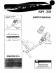
SR 30 USER'S MANUAL Model No. 831.283170 Serial No. Serial Number Decal F'Q [e,| U ||l I p _|il M E NT [e] I_i,_r., HELPLINE! 1-800-736-6879 Patent Pending SEARS, ROEBUCK AND CO., HOFFMAN ESTATES, IL 60179 www.proform.
TABLE OF CONTENTS IMPORTANT PRECAUTIONS ............................................................. BEFORE YOU BEGIN ................................................................... ASSEMBLY ........................................................................... HOW TO OPERATE THE EXERCISE CYCLE ................................................. MAINTENANCE AND TROUBLESHOOTING ................................................. CONDITIONING GUIDELINES ..................................................
BEFORE YOU BEGIN Congratulations for selecting the new PROFORM ®SR 30 exercise cycle. Cycling is one of the most effective exercises for increasing cardiovascular fitness, building endurance, and toning the entire body. The PROFORM ®SR 30 exercise cycle offers a selection of features designed to let you enjoy this healthful exercise in the convenience and privacy of your home. HELPLINE at 1-800-736-6879, Monday through Saturday, 7 a.m. until 7 p.m. Central Time (excluding holidays).
ASSEMBLY Assembly requires two persons. Place all parts of the exercise cycle in a cleared area and remove the packing materials. Do not dispose of the packing materials until assembly is compTeted. In addition to the included allen wrenches, assembly requires a phillips screwdriver _, adjustable wrench _:_::_, and a rubber mallet C an _-_ L_J As you assemble the exercise cycle, use the drawings below to identify the small parts used in assembly.
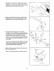
1. Identify the Front Stabilizer (2). While another person lifts the front of the Frame (1) slightly, attach the Front Stabilizer to the Frame with two M10 x 75mm Carriage Bolts (48) and two M10 Nylon Locknuts (44). 2 2. Orient the Frame Rail (3) as shown. Attach the Rear Stabilizer (5) to the Frame Rail with two M10 x 80mm Button Bolts (49) and two M10 Split Washers (43). 5 49 3. Locate the Seat Knob (not shown) on the Seat Carriage (4).
5. Heldthe SeatFrame(6)atanangle,andinsertthetab on theSeatFrameintotheindicatedslotinthe Seat Carriage(4).AttachtheSeatFrametothe Seat CarriagewithtwoM10x 66ramButtonBolts(47)and two M10SplitWashers(43). 5 6. Attachthe Backrest(9)totheSeatCarriage(4)with two M6x 16mmScrews(37),anM6x 53mmScrew (30),andanM6FlatWasher(38)as shown, 6 g\ 3O 7. TheConsole(12)requiresthree"AA"batteries(not included); alkalinebatteriesarerecommended. Insert threebatteriesintotheConsoleas shown.
9. While another person holds the Upright (11) in the position shown, connect the console wire to the Reed Switch Wire (46). Next, connect the console cable to the Lower Cable (32) in the following way: :9 • Refer to inset drawing A. Pull up on the metal bracket on the Lower Cable (32), and insed the tip of the console cable (CC) into the wire clip inside of the metal bracket. • Refer to inset drawing B.
HOW TO OPERATE THE EXERCISE CYCLE HOW TO ADJUST THE SEAT HOW TO ADJUST THE PEDALING RESISTANCE For effective exercise, the seat should be in the proper position. As you pedal, there should be a slight bend in your knees when the pedals are at the point farthest from you. To adjust the seat, first turn the seat knob counterclockwise two or three turns to loosen it (if the knob is not loosened enough, it may scratch the frame rail).
HOW TO OPERATE THE CONSOLE FEATURES OF THE CONSOLE Make sure that there are batteries in the console (see BATI-ERY REPLACEMENT on page 11). If there is a thin sheet of clear plastic on the console, remove it. Follow the steps below to operate the console. i i g:S B=_ 1. \ To turn on the power, press the On/Reset button or simply begin pedaling. When the power is turned on, the entire display will appear for two seconds. The console will then be ready for use. 2.
3. Measure your heart rate if desired. Note: If there are thin sheets of plastic on the four metal contacts of the pulse sensor, peel off the plastic. Pulse Sensor "_ To use the pulse sensor, hold the handle on the console, with your right palm covering the two right contacts and your left palm covering the two left contacts. Avoid moving your hands. When your pulse is detected, the heart-shaped indicator in the display will flash each time your heart beats and two dashes (- -) will appear.
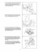
MAINTENANCE AND TROUBLESHOOTING Inspect and properly tighten all parts of the exercise cycle regularly. Replace any worn parts immediately. Using an adiustable wrench, turn the Left Pedal (20) clockwise and remove it, Next, remove the two M4 x t6mm Screws (40) from the Left Side Shield (15) and the M4 x 12ram Screw (57) from the Side Shield Cover (17). Lift off the Side Shield Cover and the Left Side Shield. To clean the exercise cycle, use a damp cloth and a small amount of mild soap.
CONDITIONING GUIDELINES During the first few minutes of exercise, your body uses easily accessible carbohydrate calories for energy. Only after the first few minutes of exercise does your body begin to use stored fat calories for energy. If your goa! is to burn fat, adjust the intensity of your exercise until your heart rate is near the lowest number in your training zone as you exercise.
SUGGESTED STRETCHES The correct form for several basic stretches is shown at the right. Move slowly as you stretch--never bounce. 1. Toe Touch Stretch Stand with your knees bent slightly and slowly bend forward from your hips. Allow your back and shoulders to relax as you reach down toward your toes as far as possible. Hold for 15 counts, then relax. Repeat 3 times. Stretches: Hamstrings, back of knees and back. 2 2. Hamstring Stretch Sit with one leg extended.
EXPLODED DRAWING--Model Key No, Qty. =.t 1 2 3 4 5 6 7 8 9 10 11 12 13 14 15 16 17 18 19 20 21 22 23 1 1 1 1 1 1 4 2 1 1 1 1 1 1 1 1 1 1 1 1 2 1 1 Description Frame Front Stabilizer Frame Rail Seat Cardage Rear Stabilizer Seat Frame Stabilizer Endcap Seat Carriage Bushing Backrest Seat Upright Console Flywheel Crank/Pulley Left Side Shield Right Side Shield Side Shield Cover Belt "C" Magnet Left Pedal Pedal Strap Right Pedal Hook No. 831.283170 Key No.
EXPLODED DRAWING--Model No. 831.283170 R0802A 7. 13.
SEARS All replacement parts are available for immediate purchase or special order when you visit your nearest SEARS Service Center. To request service or to order parts by telephone, call the toll-free numbers listed at the left. Model No. 831.