Model No. PFTL99920-INT.0 Serial No. Write the serial number in the space above for reference. USER’S MANUAL Serial Number Decal CUSTOMER SERVICE UNITED KINGDOM Call: 0330 123 1045 From Ireland: 053 92 36102 Website: iconsupport.eu E-mail: csuk@iconeurope.com Write: ICON Health & Fitness, Ltd. Unit 4, Westgate Court Silkwood Park OSSETT WF5 9TT UNITED KINGDOM AUSTRALIA Call: 1800 993 770 E-mail: australiacc@iconfitness.
TABLE OF CONTENTS WARNING DECAL PLACEMENT . . . . . . . . . . . . . . . . . . . . . . . . . . . . . . . . . . . . . . . . . . . . . . . . . . . . . . . . . . . . . . .2 IMPORTANT PRECAUTIONS. . . . . . . . . . . . . . . . . . . . . . . . . . . . . . . . . . . . . . . . . . . . . . . . . . . . . . . . . . . . . . . . . . 3 BEFORE YOU BEGIN. . . . . . . . . . . . . . . . . . . . . . . . . . . . . . . . . . . . . . . . . . . . . . . . . . . . . . . . . . . . . . . . . . . . . . . .5 PART IDENTIFICATION CHART.
IMPORTANT PRECAUTIONS WARNING: To reduce the risk of burns, fire, electric shock, or injury to persons, read all important precautions and instructions in this manual and all warnings on your treadmill before using your treadmill. ICON assumes no responsibility for personal injury or property damage sustained by or through the use of this product. 1. It is the responsibility of the owner to ensure that all users of this treadmill are adequately informed of all warnings and precautions. 12.
19. Always stand on the foot rails when starting or stopping the walking belt. Always hold the handrails while using the treadmill. frame securely in the storage position. Do not operate the treadmill while it is folded. 25. Do not change the incline of the treadmill by placing objects under the treadmill. 20. When a person is walking on the treadmill, the noise level of the treadmill will increase. 26. Never insert any object into any opening on the treadmill. 21.
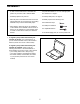
BEFORE YOU BEGIN Thank you for selecting the new PROFORM® CARBON T10 treadmill. The CARBON T10 treadmill provides an impressive selection of features designed to make your workouts at home more effective and enjoyable. reading this manual, please see the front cover of this manual. To help us assist you, note the product model number and serial number before contacting us. The model number and the location of the serial number decal are shown on the front cover of this manual.
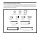
PART IDENTIFICATION CHART Use the drawings below to identify small parts used for assembly. The number in parentheses below each drawing is the key number of the part, from the PART LIST near the end of this manual. The number following the key number is the quantity used for assembly. Note: If a part is not in the hardware kit, check to see whether it is preattached. Extra parts may be included.
ASSEMBLY • To hire a service technician to assemble this product in your home, call 1-800-445-2480. • Left parts are marked “L” or “Left” and right parts are marked “R” or “Right.” • Assembly requires two persons. • To identify small parts, see page 6. • Place all parts in a cleared area and remove the packing materials. Do not dispose of the packing materials until you finish all assembly steps.
2. Make sure that the power cord is unplugged. 2 A Remove the tie securing the Upright Wire (88) to the front of the Base (97). 88 Next, identify the Right Upright (86). Have a second person hold the Right Upright near the Base (97). 88 See the inset drawing. Tie the wire tie (A) in the Right Upright (86) securely around the end of the Upright Wire (88).
4. Hold the Right Upright (86) against the Base (97). Make sure not to pinch the Upright Wire (88). 4 Insert two 3/8" x 2 3/8" Screws (3) with two 3/8" Star Washers (11) into the top of the bracket on the Right Upright (86). Partially tighten the two Screws into the Base (97); do not fully tighten the Screws yet. Then, partially tighten a 3/8" x 1 1/4" Screw (1) and a 3/8" x 1 3/4" Screw (2) with 3/8" Star Washers (11) into the bottom of the Right Upright (86); do not fully tighten the Screws yet.
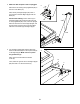
6. Identify the Left and Right Handrails (80, 81). Attach the Right Handrail (81) to the Right Upright (86) with two 5/16" x 2 1/4" Screws (7) and two 5/16" Star Washers (12) in the location shown; start both Screws, and then tighten them. Make sure not to pinch the Upright Wire (88), and make sure that the wire is on the indicated side of the Right Upright. 6 7 E 12 80 7 85 Attach the Left Handrail (80) to the Left Upright (85) in the same way. Note: There are no wires on the left side.
8. With the help of a second person, hold the console assembly (F) near the Right Upright (86). 8 F Next, insert the Upright Wire (88) through the indicated looped tie (G). Connect the Upright Wire (88) to the wire (H) from the console assembly (F). The connectors should slide together easily and snap into place. If they do not, turn one connector and try again. Then, remove any wire ties (A) from the Upright Wire (88). 88 86 9.
10. IMPORTANT: To avoid damaging the Crossbar (87), do not use power tools and do not overtighten the #10 x 3/4" Screws (6). 10 Attach the Crossbar (87) to the Handrails (80, 81) with four #10 x 3/4" Screws (6) and four 1/4" Star Washers (10); start all four Screws, and then tighten them. 10 80 6 10 87 6 10 81 11. Identify the Right Handrail Cover (79).
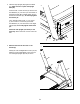
12. Carefully slide the Upright Crossbar (40) between the Left and Right Uprights (85, 86). Attach the Upright Crossbar with the four 5/16" x 3/4" Screws (8) that you removed in step 5, and four 5/16" Star Washers (12); start all four Screws, and then tighten them. 12 85 86 40 12 13. Note: If the treadmill is assembled on a smooth surface, it may roll forward during this step. 8 8 12 13 Raise the Frame (60) to the upright position. IMPORTANT: Do not raise the Frame past the vertical position.
. Remove the 5/16" Nut (39) and the 5/16" x 1 3/4" Bolt (28) from the bracket on the Base (97). 14 Next, orient the Storage Latch (35) as shown. K Attach the lower end of the Storage Latch (35) to the bracket on the Base (97) with the 5/16" x 1 3/4" Bolt (28) and the 5/16" Nut (39). 35 Then, raise the Storage Latch (35) to a vertical position, and remove the tie (K). 39 15. Remove the 5/16" Nut (39) and the 5/16" x 2 1/4" Bolt (29) from the bracket on the Latch Crossbar (31).
16. Firmly tighten the four 3/8" x 2 3/8" Screws (3), the two 3/8" x 1 1/4" Screws (1), and the two 3/8" x 1 3/4" Screws (2). 16 85 Next, set the Left Inner Base Cover (95) onto the lower end of the Left Upright (85). Then, slide the Left Base Cover (93) downward and press it onto the Left Inner Base Cover. 93 95 1 Next, set the Right Inner Base Cover (94) onto the lower end of the Right Upright (86). Then, slide the Right Base Cover (92) downward and press it onto the Right Inner Base Cover.
HOW TO USE THE TREADMILL HOW TO PLUG IN THE POWER CORD Follow the steps below to plug in the power cord. This product must be earthed. If it should malfunction or break down, earthing provides a path of least resistance for electric current to reduce the risk of electric shock. This product’s power cord has an equipment-earthing conductor and an earthing plug. IMPORTANT: If the power cord is damaged, it must be replaced with a manufacturer-recommended power cord. 1.
CONSOLE DIAGRAM See page 26 for information about purchasing an optional chest heart rate monitor. FEATURES OF THE CONSOLE The advanced treadmill console offers a selection of features designed to make your workouts more effective and enjoyable. In addition, the console features a selection of workouts. Each workout automatically controls the speed and incline of the treadmill as it guides you through an effective exercise session.
NT HOW TO TURN ON THE POWER HOW TO USE THE TOUCH SCREEN IMPORTANT: If the treadmill has been exposed to cold temperatures, allow it to warm to room temperature before you turn on the power. If you do not do this, you may damage the console displays or other electrical components. The console features a tablet with a full-color touch screen. The following information will help you become familiar with the tablet’s advanced technology: Plug in the power cord (see page 16).
HOW TO SET UP THE CONSOLE 5. Check for firmware updates. Before using the treadmill for the first time, set up the console. First, touch your name or Hello on the screen, and then touch Settings. Next, select the maintenance section. Then, touch Update to check for firmware updates using your wireless network. See step 5 on page 24 for more information. 1. Connect to your wireless network.
HOW TO USE THE MANUAL MODE 4. Change the incline of the treadmill as desired. 1. Insert the key into the console. To change the incline of the treadmill, press the Incline increase and decrease buttons or one of the numbered incline buttons. Each time you press one of the buttons, the incline will gradually change until it reaches the selected incline setting. See HOW TO TURN ON THE POWER on page 18. Note: It may take some time for the console to be ready for use. 2. Select the main menu.
7. When you are finished exercising, remove the key from the console. 3. Select a workout. To select a workout, touch the desired option on the screen. Note: The featured map workouts on your console will change periodically. If you wish to save your workout for future use, you can add it as a favorite by touching the heart button on the screen. You may also be able to either save or publish your results using one of the options on the screen. To draw your own map workout, see page 22.
HOW TO USE A DRAW YOUR OWN MAP WORKOUT 4. Save your workout. Touch Save New Workout on the screen. If desired, change the title of the workout or add a description, and then press the > symbol on the screen. Note: To use a draw your own map workout, the console must be connected to a wireless network (see HOW TO CONNECT TO A WIRELESS NETWORK on page 25). 5. Start the workout. 1. Insert the key into the console. Touch Start on the screen to start the workout.
HOW TO USE A DISTANCE OR TIME WORKOUT 5. Select a distance or time workout that you have previously added to your schedule on iFit.com. Note: To use a distance or time workout, the console must be connected to a wireless network (see HOW TO CONNECT TO A WIRELESS NETWORK on page 25). An iFit account is also required. Touch the calendar icon to download a distance or time workout from your schedule. 1. Add workouts to your schedule on iFit.com.
HOW TO CHANGE CONSOLE SETTINGS 4. View machine information. IMPORTANT: Some of the settings and features described may not be enabled. Occasionally, a firmware update may cause your console to function slightly differently. Touch Equipment Info, and then touch Machine Info to view information about your treadmill. 5. Update the console firmware. 1. Select the settings main menu. For the best results, regularly check for firmware updates.
HOW TO CONNECT TO A WIRELESS NETWORK An information box will ask if you want to connect to the wireless network. Touch Connect to connect to the network or touch Cancel to return to the list of networks. If the network has a password, touch the password entry box. A keyboard will appear on the screen. To view the password as you type it, touch the Show Password checkbox. The console is Wi-Fi enabled, allowing you to set up a wireless network connection. 1. Select the main menu. See step 2 on page 20.
HOW TO USE THE SOUND SYSTEM THE OPTIONAL HEART RATE MONITOR To play music or audio books through the console sound system while you exercise, plug a 3.5 mm male to 3.5 mm male audio cable (not included) into the jack on the console and into a jack on your personal audio player; make sure that the audio cable is fully plugged in. Note: To purchase an audio cable, see your local electronics store.
HOW TO FOLD AND MOVE THE TREADMILL HOW TO FOLD THE TREADMILL HOW TO MOVE THE TREADMILL To avoid damaging the treadmill, adjust the incline to zero before you fold the treadmill. Then, remove the key and unplug the power cord. CAUTION: You must be able to safely lift 45 lbs. (20 kg) to raise, lower, or move the treadmill. Before moving the treadmill, fold it as described at the left. CAUTION: Make sure that the storage latch is in the locked position. Moving the treadmill may require two people. 1.
MAINTENANCE AND TROUBLESHOOTING MAINTENANCE c. Check the power switch located on the treadmill frame near the power cord. If the switch protrudes as shown (A), the switch has tripped. To reset the power switch, wait for five minutes and then press the switch back in (B). Regular maintenance is important for optimal performance and to reduce wear. Inspect and properly tighten all parts each time the treadmill is used. Replace any worn parts immediately.
SYMPTOM: The displays of the console do not function properly SYMPTOM: The walking belt slows when walked on a. I f an extension cord is needed, use only a 3-conductor, 14-gauge (2 mm2) cord that is no longer than 5 ft. (1.5 m). a. Remove the key from the console and UNPLUG THE POWER CORD. Next, remove the five #8 x 3/4" Screws (4), and carefully pivot off the Motor Hood (65). b. If the walking belt is overtightened, treadmill performance may decrease and the walking belt may become damaged.
SYMPTOM: The walking belt is not centered between the foot rails SYMPTOM: The displays of the console do not function properly a. IMPORTANT: If the walking belt rubs against the foot rails (D), the walking belt may become damaged. First, remove the key and UNPLUG THE POWER CORD.
EXERCISE GUIDELINES Aerobic Exercise—If your goal is to strengthen your cardiovascular system, you must perform aerobic exercise, which is activity that requires large amounts of oxygen for prolonged periods of time. For aerobic exercise, adjust the intensity of your exercise until your heart rate is near the highest number in your training zone. WARNING: Before beginning this or any exercise program, consult your physician.
SUGGESTED STRETCHES The correct form for several basic stretches is shown at the right. Move slowly as you stretch—never bounce. 1. Toe Touch Stretch 1 Stand with your knees bent slightly and slowly bend forward from your hips. Allow your back and shoulders to relax as you reach down toward your toes as far as possible. Hold for 15 counts, then relax. Repeat 3 times. Stretches: Hamstrings, back of knees and back. 2. Hamstring Stretch Sit with one leg extended.
NOTES 33
PART LIST Key No. Qty. 1 2 3 4 5 6 7 8 9 10 11 12 13 14 15 16 17 18 19 20 21 22 23 24 25 26 27 28 29 30 31 32 33 34 35 36 37 38 39 40 41 42 43 44 45 46 47 48 49 50 2 2 4 82 11 4 4 6 1 8 8 10 2 3 2 2 1 2 4 6 1 1 2 4 4 4 7 1 1 2 1 4 2 6 1 1 5 6 4 1 1 4 1 1 1 1 1 2 1 2 Model No. PFTL99920-INT.0 R0820A Description Key No. Qty.
Key No. Qty. 101 102 103 104 105 1 1 1 1 2 Description Key No. Qty. Console Frame Reed Switch Clamp Magnet Motor Bushing 106 107 108 109 * 3 3 1 1 – Description M4 Nut M4 x 10mm Bolt Filter Motor Isolator User’s Manual Note: Specifications are subject to change without notice. For information about ordering replacement parts, see the back cover of this manual. *These parts are not illustrated.
4 36 4 14 42 51 32 39 26 34 4 63 4 20 46 64 4 62 42 8 47 14 12 4 20 34 4 63 4 49 50 26 44 61 51 32 39 34 20 25 32 39 34 45 60 20 39 4 29 4 8 53 4 103 104 42 4 12 26 52 51 102 4 35 20 34 18 84 27 4 59 4 105 42 20 36 55 39 14 58 56 34 51 32 39 50 26 106 25 23 31 28 52 84 27 27 107 107 109 18 107 108 54 27 30 EXPLODED DRAWING A Model No. PFTL99920-INT.
EXPLODED DRAWING B Model No. PFTL99920-INT.
EXPLODED DRAWING C Model No. PFTL99920-INT.
EXPLODED DRAWING D 98 5 5 5 Model No. PFTL99920-INT.
ORDERING REPLACEMENT PARTS To order replacement parts, please see the front cover of this manual.