Model No. 831.10442.0 Serial No. Write the serial number in the space above for reference. Serial Number Decal • Assembly • Operation • Maintenance • Part List and Drawing Sears, Roebuck and Co. Hoffman Estates, IL 60179 CAUTION Read all precautions and instructions in this manual before using this equipment. Keep this manual for future reference.
TABLE OF CONTENTS WARNING DECAL PLACEMENT . . . . . . . . . . . . . . . . . . . . . . . . . . . . . . . . . . . . . . . . . . . . . . . . . . . . . . . . . . . . . . .2 IMPORTANT PRECAUTIONS. . . . . . . . . . . . . . . . . . . . . . . . . . . . . . . . . . . . . . . . . . . . . . . . . . . . . . . . . . . . . . . . . . 3 BEFORE YOU BEGIN. . . . . . . . . . . . . . . . . . . . . . . . . . . . . . . . . . . . . . . . . . . . . . . . . . . . . . . . . . . . . . . . . . . . . . . .4 PART IDENTIFICATION CHART.
IMPORTANT PRECAUTIONS WARNING: To reduce the risk of serious injury, read all important precautions and instructions in this manual and all warnings on your exercise bike before using your exercise bike. Sears assumes no responsibility for personal injury or property damage sustained by or through the use of this product. 1. It is the responsibility of the owner to ensure that all users of the exercise bike are adequately informed of all precautions. 9.
BEFORE YOU BEGIN Thank you for choosing the new PROFORM® CARBON CX exercise bike. Cycling is an effective exercise for increasing cardiovascular fitness, building endurance, and toning the body. The CARBON CX exercise bike provides a selection of features designed to make your workouts at home more effective and enjoyable. reading this manual, please see the back cover of this manual. To help us assist you, note the product model number and serial number before contacting us.
PART IDENTIFICATION CHART Use the drawings below to identify the small parts needed for assembly. The number in parentheses below each drawing is the key number of the part, from the PART LIST near the end of this manual. The number following the key number is the quantity needed for assembly. Note: If a part is not in the hardware kit, check to see if it has been preassembled. Extra parts may be included. If a part is missing, please call 1-888-533-1333.
ASSEMBLY • Assembly requires two persons. one Phillips screwdriver • Place all parts in a cleared area and remove the packing materials. Do not dispose of the packing materials until you finish all assembly steps. one adjustable wrench • Left parts are marked “L” or “Left” and right parts are marked “R” or “Right.” Assembly may be easier if you have a set of wrenches.
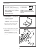
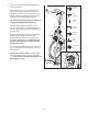
3. Attach the Rear Stabilizer (3) to the Frame (1) with two M10 x 25mm Screws (69). 3 69 3 1 4. Tip: See the inset drawing to learn how to operate the Adjustment Handle (14). 4 Loosen handle Locate the Adjustment Handle (14) on the rear of the Frame (1). Pull the Adjustment Handle outward, and insert the Saddle Post (7) into the Frame.
5. Orient the Left and Right Weight Rests (11, 12) as shown. 5 71 Attach each Weight Rest (11, 122) to the Saddle Carriage (10) with two M6 x 15mm Screws (71). 11 12 10 71 6. Note: You can attach your own pedals if desired. 6 Identify the Right Pedal (16). Using the included wrench, firmly tighten the Right Pedal clockwise into the Right Crank Arm (18). Firmly tighten the Left Pedal (17) counterclockwise into the Left Crank Arm (not shown).
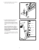
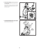
7. Have a second person hold the Handlebar (4) near the Frame (1). 7 Loosen handle Next, locate the wire tie (A) in the Frame (1). Tie the wire tie to the Upper Wire (90) in the Handlebar (4). Then, pull the lower end of the wire tie until the Upper Wire is routed through the Frame. Untie and discard the wire tie. Pull handle B 4 Tip: See the upper inset drawing to learn how to operate the Adjustment Handle (14). Next, locate the Adjustment Handle (14) on the front of the Frame (1).
8. See the inset drawing. Connect the connector on the Upper Wire (90) to the connector on the Lower Wire (82). 8 C Next, tighten the zip tie (C) around the indicated mark (D) on the Upper Wire (90). Then, cut off the excess zip tie. 82 90 C D 82 90 9. Tip: Avoid pinching the wires. Press the Motor Cover (38) onto the Frame (1), and then attach it with an M4 x 20mm Screw (87).
10. Untie the wire tie (E) holding the Upper Wire (90) to the Handlebar (4). 10 While a second person holds the Console Mount (5) near the Handlebar (4), connect the Extension Wire (99) in the Console Mount to the Upper Wire (90) in the Handlebar (4). F 5 70 Tip: Avoid pinching the wires. Gently pull on the indicated wire tie (F) as you slide the Console Mount (5) onto the Handlebar (4). Continue to pull the wire tie until the Extension Wire (99) is routed through the Console Mount.
. Orient the Console (6) and the Console Housing (86) as shown. Slide the Console into the Console Housing. 12 6 86 13. Orient the Console Housing (86) and the Console Deck (89) as shown. 13 100 100 Attach the Console Housing (86) to the Console Deck (89) with four M4 x 16mm Screws (100); start all the Screws, and then tighten them. 86 89 14. While a second person holds the Console Deck (89) near the Console Mount (5), connect the Console Wire (K) to the Extension Wire (99).
15. Tip: Avoid pinching the wires. If necessary, tilt the Console Bracket (26) upward to make this step easier. Attach the Console Deck (89) to the Console Bracket with four M4 x 12mm Screws (81); start all the Screws, and then tighten them. 15 89 Avoid pinching the wires 26 81 81 16. Set the Hand Weights (59) in the Weight Rests (11, 12). 16 59 59 11, 12 17.
HOW TO USE THE EXERCISE BIKE HOW TO LEVEL THE EXERCISE BIKE If the exercise bike rocks slightly on your floor during use, turn one or both of the leveling feet (A) beneath the rear stabilizer until the rocking motion is eliminated. Note: The carriage handle (C) functions like a ratchet. Turn the carriage handle in the desired direction, pull it outward, turn it in the opposite direction, push it inward, and then turn it in the desired direction again. Repeat this process as many times as necessary.
HOW TO ADJUST THE HANDLEBAR HOW TO USE THE PEDALS To adjust the height of the handlebar, first loosen the adjustment handle (E) four turns and pull it outward. Then, move the handlebar E upward or downward, release the adjustment handle into an adjustment hole in the handlebar, and firmly tighten the adjustment handle four turns. Make sure that the adjustment handle is engaged in an adjustment hole. Then, pull the adjustment handle outward, turn it so that it points downward as shown, and then release it.
HOW TO USE THE CONSOLE CONSOLE DIAGRAM FEATURES OF THE CONSOLE You can also connect your tablet to the console and use the iFit®–Smart Cardio Equipment app to record and track your workout information. The easy-to-use console enables you to change the resistance of the pedals with the touch of a button and provides instant exercise feedback during your workouts. To use the manual mode, see page 17. To connect your tablet to the console, see page 18.
HOW TO USE THE MANUAL MODE RPM (circular arrow icon)—This mode displays your pedaling speed, in revolutions per minute (RPM). 1. Begin pedaling or press any button on the console to turn on the console. Time (clock icon)—This mode displays the elapsed time that you have pedaled during your workout. When you turn on the console, the display will turn on. The console will then be ready for use. 2. Change the resistance of the pedals as desired.
4. Wear a heart rate monitor and measure your heart rate if desired. Then, open the iFit–Smart Cardio Equipment app and follow the instructions to set up an iFit account and customize settings. You can wear an optional heart rate monitor to measure your heart rate. For more information about the optional heart rate monitor, see page 19. Note: The console is compatible with Bluetooth® Smart heart rate monitors. 2. Connect your heart rate monitor to the console if desired.
HOW TO CONNECT YOUR HEART RATE MONITOR TO THE CONSOLE THE OPTIONAL CHEST HEART RATE MONITOR Whether your goal is to burn fat or to strengthen your cardiovascular system, the key to achieving the best results is to maintain the proper heart rate during your workouts. The optional chest heart rate monitor will enable you to continuously monitor your heart rate while you exercise, helping you to reach your personal fitness goals.
FCC INFORMATION This equipment has been tested and found to comply with the limits for a Class B digital device, pursuant to Part 15 of the FCC Rules. These limits are designed to provide reasonable protection against harmful interference in a residential installation. This equipment generates, uses, and can radiate radio frequency energy and, if not installed and used in accordance with the instructions, may cause harmful interference to radio communications.
MAINTENANCE AND TROUBLESHOOTING HOW TO MAINTAIN THE EXERCISE BIKE HOW TO ADJUST THE REED SWITCH Regular maintenance is important for optimal performance and to reduce wear. Inspect and properly tighten all parts each time the exercise bike is used. Replace any worn parts immediately. If the console does not display correct feedback, the reed switch should be adjusted. To adjust the reed switch, locate the Reed Switch (57) on the left side of the exercise bike.
HOW TO ADJUST THE DRIVE BELT Then, tighten the M10 x 60mm Screw (65) until the Drive Belt (not shown) is tight. If you feel the pedals slip while you are pedaling, even when the resistance is adjusted to the highest level, the drive belt may need to be adjusted. When the Drive Belt (not shown) is tight, reattach the Idler Cover (36). To adjust the drive belt, locate the Idler Cover (36). Remove the M4 x 12mm Blunt Screw (80) and the Idler Cover.
EXERCISE GUIDELINES Aerobic Exercise—If your goal is to strengthen your cardiovascular system, you must perform aerobic exercise, which is activity that requires large amounts of oxygen for prolonged periods of time. For aerobic exercise, adjust the intensity of your exercise until your heart rate is near the highest number in your training zone. WARNING: Before beginning this or any exercise program, consult your physician.
PART LIST Key No. Qty. 1 2 3 4 5 6 7 8 9 10 11 12 13 14 15 16 17 18 19 20 21 22 23 24 25 26 27 28 29 30 31 32 33 34 35 36 37 38 39 40 41 42 43 44 45 1 1 1 1 1 1 1 1 1 1 1 1 1 2 1 1 1 1 1 1 1 1 1 1 1 1 1 1 1 2 1 1 1 1 1 1 1 1 1 1 1 2 2 2 1 Model No. 831.10442.0 R0919B Description Key No. Qty.
Key No. Qty. 91 92 93 94 95 96 1 2 1 2 2 2 Description Key No. Qty. Pivot Spacer M8 Washer M8 x 80mm Bolt Outer Pivot Disc Inner Pivot Disc Upper/Lower Pivot Disc 97 98 99 100 * * 1 1 1 4 – – Description Center Pivot Disc Wire Protector Extension Wire M4 x 16mm Screw Assembly Tool User’s Manual Note: Specifications are subject to change without notice. For information about ordering replacement parts, see the back cover of this manual. If a part is missing, call 1-888-533-1333.
71 26 55 59 89 10 11 13 79 9 6 12 8 71 59 86 87 4 100 93 7 92 81 26 40 70 41 81 81 64 90 82 98 92 95 70 96 97 96 56 94 99 5 91 95 83 68 94 EXPLODED DRAWING A Model No. 831.10442.
67 87 25 39 17 42 87 87 66 21 87 22 27 3 57 19 88 68 30 80 27 53 69 44 14 28 23 43 87 73 20 30 77 78 29 58 65 15 84 54 87 31 76 79 80 37 44 1 43 32 80 87 61 14 80 87 74 62 64 61 80 38 24 62 80 69 36 87 80 45 75 85 35 50 80 61 2 49 18 87 52 34 64 54 47 51 80 46 49 63 42 80 61 72 48 16 33 60 85 80 75 EXPLODED DRAWING B Model No. 831.10442.
1 YEAR FULL WARRANTY If this Sears Bike Exerciser fails due to a defect in material or workmanship within 1 year of the date of purchase, call 1-800-4-MY-HOME® (1-800-469-4663) to arrange for free repair (or replacement if repair proves impossible). The frame is warranted for 10 years from the date of purchase. This warranty does not apply when the Bike Exerciser is used commercially or for rental purposes.