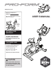
www.proform.com Model No. PFEX01215.0 Serial No. Write the serial number in the space above for reference. Serial Number Decal ACTIVATE YOUR WARRANTY To register your product and activate your warranty today, go to www.proformservice.com/ registration. CUSTOMER CARE For service at any time, go to www.proformservice.com. Or call 1-877-660-1168 Mon.–Fri. 6 a.m.–6 p.m. MT Sat. 8 a.m.–12 p.m. MT Please do not contact the store.
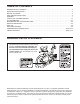
TABLE OF CONTENTS WARNING DECAL PLACEMENT . . . . . . . . . . . . . . . . . . . . . . . . . . . . . . . . . . . . . . . . . . . . . . . . . . . . . . . . . . . . . . .2 IMPORTANT PRECAUTIONS . . . . . . . . . . . . . . . . . . . . . . . . . . . . . . . . . . . . . . . . . . . . . . . . . . . . . . . . . . . . . . . . . . 3 BEFORE YOU BEGIN. . . . . . . . . . . . . . . . . . . . . . . . . . . . . . . . . . . . . . . . . . . . . . . . . . . . . . . . . . . . . . . . . . . . . . . .
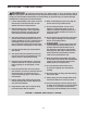
IMPORTANT PRECAUTIONS WARNING: To reduce the risk of burns, fire, electric shock, or injury to persons, read all important precautions and instructions in this manual and all warnings on your exercise bike before using your exercise bike. ICON assumes no responsibility for personal injury or property damage sustained by or through the use of this product. 1. It is the responsibility of the owner to ensure that all users of the exercise bike are adequately informed of all precautions. 10.
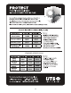
STANDARD SERVICE PLANS all 4
BEFORE YOU BEGIN Congratulations for selecting the revolutionary PROFORM® LE TOUR DE FRANCE® exercise bike. The LE TOUR DE FRANCE exercise bike is unlike any other exercise bike. With an incline system that allows you to simulate actual terrain and an array of other features, the LE TOUR DE FRANCE exercise bike is designed to let you enjoy the outdoor cycling experience indoors. reading this manual, please see the front cover of this manual.
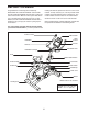
PART IDENTIFICATION CHART Use the drawings below to identify the small parts needed for assembly. The number in parentheses below each drawing is the key number of the part, from the PART LIST near the end of this manual. The number following the key number is the quantity needed for assembly. Note: If a part is not in the hardware kit, check to see whether it has been preassembled. Extra parts may be included.
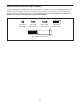
ASSEMBLY • To hire an authorized service technician to assemble the exercise bike, call 1-800-445-2480. • To identify small parts, see page 6. • In addition to the included tool(s), assembly requires the following tools: • Assembly requires two persons. one Phillips screwdriver • Place all parts in a cleared area and remove the packing materials. Do not dispose of the packing materials until you complete all assembly steps. Assembly may be easier if you have your own set of wrenches.
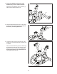
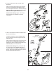
3. If there are shipping screws in the Front Stabilizer (22), remove and discard them. 3 Attach the Front Stabilizer (22) to the Base (1) with two M10 x 58mm Screws (74). 74 22 74 1 4. Attach the Water Bottle Holder (8) to the Frame (2) with two #8 x 10mm Screws (110); start all the Screws, and then tighten them. 4 8 110 2 5. Locate the Post Knob (47) near the rear of the Frame (2). Loosen the Post Knob, and then pull it outward.
6. Loosen the Seat Knob (29), and then pull it downward. 6 Next, insert the Seat Carriage (4) into the Seat Post (3), and release the Seat Knob (29) into one of the adjustment holes in the Seat Carriage. Make sure that the Seat Knob is in an adjustment hole. Then, tighten the Seat Knob. 4 3 See the inset drawing. Tighten a #8 x 6mm Screw (92) into the underside of the Seat Carriage (4). 29 4 92 7. Have a second person hold the Handlebar Post (6) near the Frame (2).
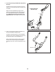
8. Tip: Avoid pinching the Main Wire (68) during this step. 8 Locate the Post Knob (47) near the front of the Frame (2). Loosen the Post Knob, and then pull it outward. Avoid pinching the Main Wire (68) Next, insert the Handlebar Post (6) into the Frame (2), and release the Post Knob (47) into one of the adjustment holes in the Handlebar Post. Make sure that the Post Knob is in an adjustment hole. Then, tighten the Post Knob. 6 2 68 47 9.
10. Tip: Avoid pinching the wires during this step. 10 Avoid pinching the wires Attach the Handlebar (7) to the Handlebar Carriage (105) with four M6 x 16mm Screws (103); start all the Screws, and then tighten them. 103 7 105 11. Tip: Avoid pinching the wires during this step. 11 Avoid pinching the wires 9 Have a second person hold the Console (9) near the Handlebar Carriage (105).
. Identify the Right Pedal (62). 12 Using the included flat wrench tool, firmly tighten the Right Pedal (62) clockwise into the Right Crank Arm (64). Firmly tighten the Left Pedal (61) counterclockwise into the Left Crank Arm (not shown). IMPORTANT: You must turn the Left Pedal counterclockwise to attach it. 61 To adjust the straps on the Pedals (61, 62), see HOW TO USE THE PEDALS on page 15. 64 62 13.
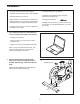
HOW TO USE THE EXERCISE BIKE HOW TO PLUG IN THE POWER CORD A temporary adapter may be used to connect the power cord to a 2-pole receptacle as shown at the right if a properly grounded outlet is not available. This product must be grounded. If it should malfunction or break down, grounding provides a path of least resistance for electric current to reduce the risk of electric shock. The power cord has a plug with a grounding pin.
HOW TO ADJUST THE HEIGHT OF THE SEAT HOW TO ADJUST THE HEIGHT OF THE HANDLEBAR For effective exercise, the seat should be at the proper height. As you pedal, there should be a slight bend in your knees when the pedals are in the lowest position. To adjust the height of the handlebar, first loosen the post knob and pull it outward. Then, move the handlebar post upward or downward, release the post knob into an adjustment hole in the handlebar post, and firmly tighten the post knob.
HOW TO USE THE PEDALS HOW TO USE THE TABLET HOLDER To use the pedals, insert your shoes into the toe cages, and pull the ends of the toe straps. To adjust the toe straps, press and hold the tabs on the buckles, adjust the toe straps to the desired position, and then release the tabs. IMPORTANT: The tablet holder is designed for use with most small tablets. Do not place any other electronic device or object into the tablet holder.
CONSOLE DIAGRAM FEATURES OF THE CONSOLE The console also offers a selection of onboard workouts. Each workout automatically changes the incline (resistance) of the exercise bike and allows you to change gears to maintain your pedaling cadence. The advanced console offers an array of features designed to make your workouts more effective and enjoyable. You can also listen to your favorite workout music or audio books with the console sound system while you exercise.
HOW TO TURN ON THE POWER HOW TO USE THE MANUAL MODE IMPORTANT: If the exercise bike has been exposed to cold temperatures, allow it to warm to room temperature before you turn on the power. If you do not do this, you may damage the console displays or other electrical components. 1. Begin pedaling or press any button on the console to turn on the console. Plug in the power cord (see HOW TO PLUG IN THE POWER CORD on page 13). Next, locate the power switch on the frame near the power cord.
5. Change gears as desired. 7. Follow your progress with the power ring, and set a power output target, if desired. Note: The exercise bike has simulated gears; there are no actual gears. The power ring will provide a visual representation of your power output in watts per kilogram of body weight. As your power output increases or decreases, a solid bar will appear or disappear in the power ring. As you pedal, you can change gears to make pedaling easier or harder.
IMPORTANT: The power output target is intended only to provide motivation. Make sure to pedal at a speed, a gear setting, and an incline level that is comfortable for you. Scan mode—The console also has a scan mode that will display workout information in a repeating cycle. To select the scan mode, press the Display button repeatedly until the word SCAN appears in the display.
HOW TO USE AN ONBOARD WORKOUT The power ring will show a flashing indicator that represents the power output target for the segment. The solid bar represents your actual power output Note: In the power ring, power output is displayed in watts per kilogram of body weight. 1. Begin pedaling or press any button on the console to turn on the console. See HOW TO TURN ON THE POWER on page 17. Actual Power Output 2. Enter your weight.
HOW TO USE THE SOUND SYSTEM HOW TO CONNECT YOUR SMART DEVICE TO THE CONSOLE To play music or audio books through the console sound system while you exercise, plug a 3.5 mm male to 3.5 mm male audio cable (not included) into the jack on the console and into a jack on your MP3 player, CD player, or other personal audio player; make sure that the audio cable is fully plugged in. Note: To purchase an audio cable, see your local electronics store.
HOW TO CONNECT YOUR HEART RATE MONITOR TO THE CONSOLE 3. Change settings as desired. Change the Unit of Measurement—The display will alternate showing the console version number and the unit of measurement. The console is compatible with all BLUETOOTH Smart heart rate monitors. To connect your BLUETOOTH Smart heart rate monitor to the console, press the Bluetooth Smart button on the console. When a connection is established, the LED on the console will flash red twice.
FCC INFORMATION This equipment has been tested and found to comply with the limits for a Class B digital device, pursuant to part 15 of the FCC Rules. These limits are designed to provide reasonable protection against harmful interference in a residential installation. This equipment generates, uses, and can radiate radio frequency energy and, if not installed and used in accordance with the instructions, may cause harmful interference to radio communications.
MAINTENANCE AND TROUBLESHOOTING HOW TO MAINTAIN THE EXERCISE BIKE Next, remove the four #8 x 1/2” Screws (95) and the Electronics Shield (98). Then, locate the Reed Switch (35), and loosen the two #8 x 19mm Tek Screws (97). Regular maintenance is important for optimal performance and to reduce wear. Inspect and properly tighten all parts each time the exercise bike is used. Replace any worn parts immediately. 98 To clean the exercise bike, use a damp cloth and a small amount of mild detergent.
HOW TO ADJUST THE DRIVE BELT If the pedals slip while you are pedaling, the drive belt may need to be adjusted. 66 To adjust the drive belt, first press the power switch to the off position and unplug the power cord. Next, locate the access hole in the underside of the Right Shield (12). Insert a hex key into the access hole, and tighten the Idler Adjustment Screw (not shown) slightly. Access Hole Then, plug in the power cord and press the power switch to the reset position.
EXERCISE GUIDELINES Aerobic Exercise—If your goal is to strengthen your cardiovascular system, you must perform aerobic exercise, which is activity that requires large amounts of oxygen for prolonged periods of time. For aerobic exercise, adjust the intensity of your exercise until your heart rate is near the highest number in your training zone. WARNING: Before beginning this or any exercise program, consult your physician.
SUGGESTED STRETCHES The correct form for several basic stretches is shown at the right. Move slowly as you stretch; never bounce. 1. Toe Touch Stretch Stand with your knees bent slightly and slowly bend forward from your hips. Allow your back and shoulders to relax as you reach down toward your toes as far as possible. Hold for 15 counts, then relax. Repeat 3 times. Stretches: Hamstrings, back of knees and back. 1 2. Hamstring Stretch Sit with one leg extended.
PART LIST Key No. Qty. 1 2 3 4 5 6 7 8 9 10 11 12 13 14 15 16 17 18 19 20 21 22 23 24 25 26 27 28 29 30 31 32 33 34 35 36 37 38 39 40 41 42 43 44 45 46 47 48 49 50 1 1 1 1 1 1 1 1 1 1 1 1 2 1 1 1 1 1 1 2 2 1 1 4 2 2 2 2 1 1 1 1 1 1 1 1 1 1 1 1 1 1 1 1 1 2 2 1 1 1 Model No. PFEX01215.0 R1015A Description Key No. Qty.
Key No. Qty. 101 102 103 104 105 106 107 1 2 4 1 1 1 1 Description Key No. Qty. Receiver/Wire #8 x 1/2" Self-tapping Screw M6 x 16mm Screw Handlebar Carriage Cap Handlebar Carriage Brake Pad/Locks Handlebar Knob 108 109 110 111 112 * * 1 2 2 2 4 – – Description Spring 1/4" Locknut #8 x 10mm Screw #8 x 6mm Screw #8 x 19mm Screw Assembly Tool User’s Manual Note: Specifications are subject to change without notice. For information about ordering replacement parts, see the back cover of this manual.
71 42 40 95 15 30 67 82 41 33 43 82 32 44 95 18 59 71 85 19 45 108 14 86 71 37 35 36 87 85 34 31 97 93 52 21 74 88 58 57 39 25 23 30 99 96 51 89 86 47 100 20 109 38 50 95 1 24 2 8 20 95 60 73 80 94 49 48 57 77 59 83 98 95 54 88 21 22 53 55 27 17 74 55 80 110 76 89 66 16 79 26 84 24 75 27 84 EXPLODED DRAWING A Model No. PFEX01215.
13 88 94 78 65 61 63 91 102 28 5 92 90 4 11 56 88 12 28 10 29 13 3 91 46 78 65 64 102 69 62 46 103 6 72 70 112 89 68 111 104 107 7 81 105 9 89 89 106 94 101 94 EXPLODED DRAWING B Model No. PFEX01215.
ORDERING REPLACEMENT PARTS To order replacement parts, please see the front cover of this manual.