Model No. PFEVEX77918.0 Serial No. Write the serial number in the space above for reference. USER’S MANUAL Serial Number Decal CUSTOMER SERVICE UNITED KINGDOM Call: 0330 123 1045 From Ireland: 053 92 36102 Website: iconsupport.eu E-mail: csuk@iconeurope.com Write: ICON Health & Fitness, Ltd. Unit 4, Westgate Court Silkwood Park OSSETT WF5 9TT UNITED KINGDOM AUSTRALIA Call: 1800 993 770 E-mail: australiacc@iconfitness.
TABLE OF CONTENTS WARNING DECAL PLACEMENT . . . . . . . . . . . . . . . . . . . . . . . . . . . . . . . . . . . . . . . . . . . . . . . . . . . . . . . . . . . . . . .2 IMPORTANT PRECAUTIONS. . . . . . . . . . . . . . . . . . . . . . . . . . . . . . . . . . . . . . . . . . . . . . . . . . . . . . . . . . . . . . . . . . 3 BEFORE YOU BEGIN. . . . . . . . . . . . . . . . . . . . . . . . . . . . . . . . . . . . . . . . . . . . . . . . . . . . . . . . . . . . . . . . . . . . . . . .4 PART IDENTIFICATION CHART.
IMPORTANT PRECAUTIONS WARNING: To reduce the risk of serious injury, read all important precautions and instructions in this manual and all warnings on your exercise bike before using your exercise bike. ICON assumes no responsibility for personal injury or property damage sustained by or through the use of this product. 1. It is the responsibility of the owner to ensure that all users of the exercise bike are adequately informed of all precautions. 9.
BEFORE YOU BEGIN Thank you for choosing the new PROFORM® SMART POWER 10.0 exercise bike. Cycling is an effective exercise for increasing cardiovascular fitness, building endurance, and toning the body. The SMART POWER 10.0 exercise bike provides a selection of features designed to make your workouts at home more effective and enjoyable. reading this manual, please see the front cover of this manual. To help us assist you, note the product model number and serial number before contacting us.
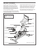
PART IDENTIFICATION CHART Use the drawings below to identify the small parts needed for assembly. The number in parentheses below each drawing is the key number of the part, from the PART LIST near the end of this manual. The number following the key number is the quantity needed for assembly. Note: If a part is not in the hardware kit, check to see if it has been preassembled. Extra parts may be included.
ASSEMBLY • Assembly requires two persons. one Phillips screwdriver • Place all parts in a cleared area and remove the packing materials. Do not dispose of the packing materials until you finish all assembly steps. one adjustable wrench • Left parts are marked “L” or “Left” and right parts are marked “R” or “Right.” one pair of scissors one rubber mallet Assembly may be easier if you have a set of wrenches. To avoid damaging parts, do not use power tools.
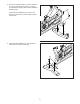
2. If there are shipping tubes (not shown) attached to the front and rear of the Frame (1), remove and discard the shipping tubes and the hardware attaching them. 2 69 Orient the Front Stabilizer (2) as shown, and attach it to the Frame (1) with two M10 x 25mm Screws (69). 1 2 3. Attach the Rear Stabilizer (3) to the Frame (1) with two M10 x 25mm Screws (69).
4. Tip: See the inset drawing to learn how to operate the Adjustment Handle (14). 4 Loosen handle Locate the Adjustment Handle (14) on the rear of the Frame (1). Pull the Adjustment Handle outward, and insert the Saddle Post (7) into the Frame. Pull handle Adjust post Next, move the Saddle Post (7) upward or downward to the desired position, release the Adjustment Handle (14) into an adjustment hole in the Saddle Post, and then tighten the Adjustment Handle four turns.
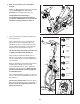
6. Note: You can attach your own pedals if desired. 6 Identify the Right Pedal (16). Using the included wrench, firmly tighten the Right Pedal clockwise into the Right Crank Arm (18). Firmly tighten the Left Pedal (17) counterclockwise into the Left Crank Arm (not shown). IMPORTANT: You must turn the Left Pedal counterclockwise to attach it. 18 16 17 7. Have a second person hold the Handlebar (4) near the Frame (1). 7 Loosen handle Next, locate the wire tie (A) in the Frame (1).
8. See the inset drawing. Connect the connector on the Upper Wire (B) to the connector on the Lower Wire (82). 8 D Next, tighten the zip tie (D) around the indicated mark (E) on the Upper Wire (B). Then, cut off the excess zip tie. 82 B D E 82 B 9. Tip: Avoid pinching the wires. Press the Motor Cover (38) onto the Frame (1), and then attach it with an M4 x 20mm Screw (87).
10. While a second person holds the Console Mount (5) near the Handlebar (4), connect the 6-pin and 8-pin Wires (90, 91) in the Console Mount to the matching connectors on the Upper Wire (B) in the Handlebar. 10 F Avoid pinching the wires Tip: Avoid pinching the wires. Gently pull on the wires in the indicated location (F) as you slide the Console Mount (5) onto the Handlebar (4). Make sure that the wires inside the Handlebar are out of the way of the bolt holes.
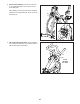
. Have a second person hold the Console (6) near the Console Bracket (26). 12 6 Plug the 6-pin and 8-pin Wires (90, 91) into the matching receptacles on the back of the Console (6); make sure to plug the Wire marked with red into the receptacle marked with red, and plug the Wire marked with yellow into the receptacle marked with yellow. Make sure that the flat side of each Wire is facing outward. 81 90, 91 Tip: Avoid pinching the wires.
14. Plug the Power Adapter (86) into the receptacle in the Frame (1). 14 Note: To plug the Power Adapter (86) into an outlet see HOW TO PLUG IN THE POWER ADAPTER on page 14. 1 86 15. After the exercise bike is assembled, inspect it to make sure that it is assembled correctly, that it functions properly, and that all parts are properly tightened. Extra parts may be included. Place a mat under the exercise bike to protect the floor or carpet.
HOW TO USE THE EXERCISE BIKE HOW TO PLUG IN THE POWER ADAPTER HOW TO ADJUST THE ANGLE OF THE SADDLE IMPORTANT: If the exercise bike has been exposed to cold temperatures, allow it to warm to room temperature before you plug in the power adapter (A). If you do not do this, you may damage the console displays or other electronic components. You can adjust the angle of the saddle to the position that is most comfortable.
HOW TO ADJUST THE SADDLE POST HOW TO ADJUST THE HANDLEBAR For effective exercise, the saddle should be at the proper height. As you pedal, there should be a slight bend in your knees when the pedals are in the lowest position. To adjust the height of the handlebar, first loosen the adjustment handle (F) four turns and pull it outward. Then, move the handlebar F upward or downward, release the adjustment handle into an adjustment hole in the handlebar, and firmly tighten the adjustment handle four turns.
HOW TO USE THE PEDALS HOW TO USE THE BRAKE KNOB To use the pedals (G), insert your shoes into the toe cages and pull the ends of the toe straps. To adjust the toe straps, press and hold the G tabs on the buckles, adjust the toe straps to the desired position, and then release the tabs. To change the resistance of the pedals, press the buttons on the console (see step 3 on page 20). To stop the flywheel, push the brake knob (H) downward. The flywheel should quickly come to a complete stop.
CONSOLE DIAGRAM FEATURES OF THE CONSOLE When you use the manual mode of the console, you can change the resistance of the pedals with the touch of a button. The advanced console offers an array of features designed to make your workouts more effective and enjoyable. While you exercise, the console will display continuous exercise feedback. You can also measure your heart rate using an optional chest heart rate monitor (see page 27 for more information).
HOW TO ACTIVATE THE CONSOLE HOW TO USE THE TOUCH SCREEN The included power adapter must be used to operate the exercise bike. See HOW TO PLUG IN THE POWER ADAPTER on page 14. When the power adapter is plugged in, simply touch the screen to activate the console. The console features a tablet with a full-color touch screen. The following information will help you use the touch screen: • The console functions similarly to other tablets.
HOW TO SET UP THE CONSOLE 5. Check for firmware updates. Before you use the exercise bike for the first time, set up the console. First, touch the profile button, touch Settings, touch Maintenance, and then touch Update. The console will check for firmware updates. For more information, see HOW TO CHANGE CONSOLE SETTINGS on page 25. 1. Connect to your wireless network. To use iFit workouts and to use several other features of the console, the console must be connected to a wireless network.
HOW TO USE THE MANUAL MODE 1. Touch the screen or press any button on the console to turn on the console. To select the desired display mode or to view statistics and charts, drag downward on the screen. You can also touch the more button (+ symbol) to view statistics or charts. See HOW TO ACTIVATE THE CONSOLE on page 18. Note: It may take a few moments for the console to be ready for use.
HOW TO USE A MAP WORKOUT OR AN ONBOARD WORKOUT To draw your own map for a workout, see HOW TO CREATE A DRAW-YOUR-OWN-MAP WORKOUT on page 23. 1. Touch the screen or press any button on the console to turn on the console. See HOW TO ACTIVATE THE CONSOLE on page 18. Note: It may take a few moments for the console to be ready for use.
If the resistance level is too high or too low, you can manually override the setting by pressing the Digital Quick Resistance buttons. If you press a Digital Quick Resistance button, you can then manually control the resistance level (see step 3 on page 20). To return to the programmed resistance settings of the workout, touch Follow Workout. When the workout comes to an end, a workout summary will appear on the screen. If desired, you can publish your results using one of the options on the screen.
HOW TO CREATE A DRAW-YOUR-OWN-MAP WORKOUT If you make a mistake, touch Undo on the left side of the screen. 1. Touch the screen or press any button on the console to turn on the console. The screen will display the elevation and distance statistics for your workout. See HOW TO ACTIVATE THE CONSOLE on page 18. Note: It may take a few moments for the console to be ready for use. 4. Save your workout. Touch Save New Workout to save your workout.
HOW TO USE AN IFIT WORKOUT To switch users within your iFit account, touch the profile button, and then touch Manage Accounts. If more than one user is associated with the account, a list of users will appear. Touch the name of the desired user. To use an iFit workout, the console must be connected to a wireless network (see HOW TO CONNECT TO A WIRELESS NETWORK on page 26). An iFit account is also required. 1. Add workouts to your schedule on iFit.com. 4.
HOW TO CHANGE CONSOLE SETTINGS 3. View the console tour presentation. IMPORTANT: Some of the settings and features described may not be enabled. Occasionally, a firmware update may cause your console to function slightly differently. To view a tour presentation that will guide you through the features of the console, touch How It Works. 1. Select the settings main menu. 4. Customize the unit of measurement and other settings.
HOW TO CONNECT TO A WIRELESS NETWORK Note: You must have your own wireless network and an 802.11b/g/n router with SSID broadcast enabled (hidden networks are not supported). To use iFit workouts and to use several other features of the console, the console must be connected to a wireless network. When a list of networks appears, touch the desired network. Note: You will need to know your network name (SSID). If your network has a password, you will also need to know the password. 1.
HOW TO USE THE SOUND SYSTEM THE OPTIONAL CHEST HEART RATE MONITOR To play music or audio books through the console sound system while you exercise, plug a 3.5 mm male to 3.5 mm male audio cable (not included) into the jack on the right side of the console and into a jack on your personal audio player; make sure that the audio cable is fully plugged in. Note: To purchase an audio cable, see your local electronics store.
MAINTENANCE AND TROUBLESHOOTING HOW TO MAINTAIN THE EXERCISE BIKE If a replacement power adapter is needed, call the telephone number on the cover of this manual. IMPORTANT: To avoid damaging the console, use only a manufacturer-supplied regulated power adapter. Regular maintenance is important for optimal performance and to reduce wear. Inspect and properly tighten all parts each time the exercise bike is used. Replace any worn parts immediately.
HOW TO ADJUST THE REED SWITCH HOW TO ADJUST THE DRIVE BELT If the console does not display correct feedback, the reed switch should be adjusted. If you feel the pedals slip while you are pedaling, even when the resistance is adjusted to the highest level, the drive belt may need to be adjusted. To adjust the reed switch, first unplug the power adapter. Next, locate the Reed Switch (57) on the left side of the exercise bike. Slightly loosen the two M4 x 20mm Screws (87).
EXERCISE GUIDELINES Aerobic Exercise—If your goal is to strengthen your cardiovascular system, you must perform aerobic exercise, which is activity that requires large amounts of oxygen for prolonged periods of time. For aerobic exercise, adjust the intensity of your exercise until your heart rate is near the highest number in your training zone. WARNING: Before beginning this or any exercise program, consult your physician.
SUGGESTED STRETCHES The correct form for several basic stretches is shown at the right. Move slowly as you stretch; never bounce. 1. Toe Touch Stretch Stand with your knees bent slightly and slowly bend forward from your hips. Allow your back and shoulders to relax as you reach down toward your toes as far as possible. Hold for 15 counts, then relax. Repeat 3 times. Stretches: Hamstrings, back of knees and back. 1 2. Hamstring Stretch Sit with one leg extended.
PART LIST Key No. Qty. 1 2 3 4 5 6 7 8 9 10 11 12 13 14 15 16 17 18 19 20 21 22 23 24 25 26 27 28 29 30 31 32 33 34 35 36 37 38 39 40 41 42 43 44 45 1 1 1 1 1 1 1 1 1 1 1 1 1 2 1 1 1 1 1 1 1 1 1 1 1 1 1 1 1 2 1 1 1 1 1 1 1 1 1 1 1 2 2 2 1 Model No. PFEVEX77918.0 R0119A Description Key No. Qty.
Key No. Qty. 91 92 93 94 95 96 97 1 2 1 2 2 2 1 Description Key No. Qty. 8-pin Wire M8 Washer M8 x 80mm Bolt Outer Pivot Disc Inner Pivot Disc Upper/Lower Pivot Disc Center Pivot Disc 98 99 100 101 102 * * 1 1 1 1 1 – – Description Wire Protector Pivot Spacer Brake Shaft End Hairpin Cotter Pin Brake Washer Assembly Tool User’s Manual Note: Specifications are subject to change without notice. For information about ordering replacement parts, see the back cover of this manual.
71 55 11 59 10 13 79 9 8 12 34 71 59 87 7 6 40 4 93 92 41 70 64 89 92 81 26 98 95 90 96 97 82 70 96 81 94 86 5 94 91 95 83 99 56 68 EXPLODED DRAWING A Model No. PFEVEX77918.
67 87 39 25 17 42 87 87 66 21 35 3 57 19 43 22 53 69 44 14 23 87 30 88 68 100 80 27 102 73 28 30 87 87 20 77 101 78 29 84 54 87 15 31 58 65 76 80 79 37 44 1 43 32 80 87 61 14 80 62 87 80 80 45 18 87 52 61 80 2 49 35 50 62 85 24 38 36 69 74 64 61 80 87 75 54 63 34 64 47 51 80 63 46 49 42 16 61 80 72 48 85 80 33 60 75 EXPLODED DRAWING B Model No. PFEVEX77918.
ORDERING REPLACEMENT PARTS To order replacement parts, please see the front cover of this manual.