Model No. PFEVEL74917.1 Serial No. Write the serial number in the space above for reference. USER’S MANUAL Serial Number Decal CUSTOMER SERVICE UNITED KINGDOM Call: 0330 123 1045 From Ireland: 053 92 36102 Website: iconsupport.eu E-mail: csuk@iconeurope.com Write: ICON Health & Fitness, Ltd. Unit 4, Westgate Court Silkwood Park OSSETT WF5 9TT UNITED KINGDOM AUSTRALIA Call: 1800 993 770 E-mail: australiacc@iconfitness.
TABLE OF CONTENTS WARNING DECAL PLACEMENT . . . . . . . . . . . . . . . . . . . . . . . . . . . . . . . . . . . . . . . . . . . . . . . . . . . . . . . . . . . . . . .2 IMPORTANT PRECAUTIONS. . . . . . . . . . . . . . . . . . . . . . . . . . . . . . . . . . . . . . . . . . . . . . . . . . . . . . . . . . . . . . . . . . 3 BEFORE YOU BEGIN. . . . . . . . . . . . . . . . . . . . . . . . . . . . . . . . . . . . . . . . . . . . . . . . . . . . . . . . . . . . . . . . . . . . . . . .4 PART IDENTIFICATION CHART.
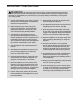
IMPORTANT PRECAUTIONS WARNING: To reduce the risk of serious injury, read all important precautions and instructions in this manual and all warnings on your elliptical before using your elliptical. ICON assumes no responsibility for personal injury or property damage sustained by or through the use of this product. 1. It is the responsibility of the owner to ensure that all users of the elliptical are adequately informed of all precautions. 9.
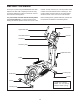
BEFORE YOU BEGIN Thank you for purchasing the PROFORM® 525 CSE + elliptical. The 525 CSE + elliptical provides an array of features designed to make your workouts at home more effective and enjoyable. manual. To help us assist you, note the product model number and serial number before contacting us. The model number and the location of the serial number decal are shown on the front cover of this manual. For your benefit, read this manual carefully before you use the elliptical.
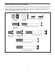
PART IDENTIFICATION CHART Use the drawings below to identify the small parts needed for assembly. The number in parentheses below each drawing is the key number of the part, from the PART LIST near the end of this manual. The number following the key number is the quantity needed for assembly. Note: If a part is not in the hardware kit, check to see if it has been preassembled. Extra parts may be included.
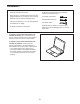
ASSEMBLY • Assembly requires two persons. • In addition to the included tool(s), assembly requires the following tool(s): • Place all parts in a cleared area and remove the packing materials. Do not dispose of the packing materials until you finish all assembly steps. one Phillips screwdriver two adjustable wrenches • Left parts are marked “L” or “Left” and right parts are marked “R” or “Right.” one rubber mallet Assembly may be easier if you have a set of wrenches.
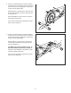
2. If there is a shipping tube (not shown) attached to the Frame (1), remove the screws (not shown) and then remove the shipping tube. Discard the screws and the shipping tube. 2 With the help of a second person, place some of the packing materials (not shown) under the rear of the Frame (1). Attach a Stabilizer (3) to the Frame (1) with two M10 x 82mm Screws (70). Then, remove the packing materials from under the rear of the Frame (1). 3 1 70 3.
4. With the help of a second person, raise the Upright (2) to the vertical position. 4 Secure the Upright (2) to the Frame (1) with an M10 x 75mm Bolt (61), an M10 x 80mm Bolt (86), and two M10 Locknuts (62); insert both Bolts, and then tighten the Locknuts. 2 Then, tighten the indicated M10 Locknut (A). 62 61 A 86 62 5. Identify the Rear Shield Cover (27) and the Front Shield Cover (28), and orient them as shown.
6. Attach the Rear Upright Cover (25) to the Upright (2) with three M4 x 16mm Screws (78); start all the Screws, and then tighten them. 6 78 24 Then, insert the Accessory Tray (24) into the Rear Upright Cover (25). 25 78 7. Orient the Front Upright Cover (26) so that the word “UP” is at the top. 2 7 26 Attach the Front Upright Cover (26) to the Rear Upright Cover (25) with two M4 x 16mm Screws (78).
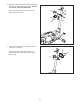
8. Using a plastic bag to keep your fingers clean, apply a generous amount of the included grease to the axles on the Upright (2). 8 Next, slide a Pivot Spacer (55) onto the right axle on the Upright (2). 2 Then, identify the Right Upper Body Arm (10), orient it as shown, and slide it onto the right axle on the Upright (2). 55 83 Attach the Right Upper Body Arm (10) with an M8 x 20mm Screw (84) and an M8 Washer (83). Grease Repeat this step on the other side of the elliptical. 9.
10. Identify the Right Pedal (7), and orient it as shown. 10 Attach the Right Pedal (7) to the Right Pedal Arm (17) with three M10 x 15mm Screws (67); start all the Screws, and then tighten them. Make sure to use the center hole and the two outer holes to attach the Right Pedal. 7 17 Repeat this step on the other side of the elliptical. 67 11. Apply a small amount of grease to an M8 x 76mm Shoulder Screw (63).
. Identify a Rear Leg Cover (38) and a Front Leg Cover (39), and orient them as shown. 12 Press the Rear and Front Leg Covers (38, 39) together around the right Upper Body Leg (13), and attach them with three M4 x 16mm Screws (78); start the center Screw first, and then start the other two Screws. Then, tighten all the Screws. Repeat this step on the other side of the elliptical. 78 13 39 38 13. Have a second person hold the Handlebar (22) in place around the Upright (2).
14. Untie and discard the wire tie attached to the Main Wire (89). 14 While a second person holds the Console (5) near the Upright (2), plug the Main Wire (89) and the Pulse Wires (23) into the receptacles on the Console. Avoid pinching the wires 5 89 The connectors on the Main Wire (89) and the Pulse Wires (23) should slide easily into the receptacles and snap into place. If a connector does not slide easily into a receptacle, turn the connector and try again.
HOW TO USE THE ELLIPTICAL HOW TO PLUG IN THE POWER ADAPTER HOW TO VARY THE MOTION OF THE PEDALS IMPORTANT: If the elliptical has been exposed to cold temperatures, allow it to warm to room temperature before you plug in the power adapter (A). If you do not do this, you may damage the console displays or other electronic components.
HOW TO MOVE THE ELLIPTICAL HOW TO EXERCISE ON THE ELLIPTICAL Turn each leveling cap (B) to the transport position; in the transport position, the caster beside each leveling cap will touch the floor. Next, hold the upright (G) and carefully move the elliptical to the desired location. Then, turn each leveling cap until the casters are not touching the floor and the elliptical is level on your floor.
CONSOLE DIAGRAM FEATURES OF THE CONSOLE a target pedaling speed as it guides you through an effective workout. The advanced console offers an array of features designed to make your workouts more effective and enjoyable. You can even listen to your favorite workout music or audio books with the console sound system while you exercise. When you use the manual mode of the console, you can change the resistance of the pedals with the touch of a button. To use the manual mode, see page 17.
HOW TO USE THE MANUAL MODE approximate number of calories you have burned. When calorie workouts are selected, the approximate number of calories that remain to be burned in the workout. 1. Begin pedaling or press any button on the console to turn on the console. When you turn on the console, the display will turn on. The console will then be ready for use. Calories per Hour (CALS/HR)—The approximate number of calories you are burning per hour. 2. Select the manual mode.
Scan mode—The console also has a scan mode that will display workout information in a repeating cycle. To turn on the scan mode, press the Scan button (B); the scan indicator (D) and the word SCAN will turn on in the display. To pause the console, simply stop pedaling or press the End button. When the console is paused, the time will flash in the display. To continue your workout, simply resume pedaling. To end the workout, press the End button repeatedly.
When your pulse is detected, your heart rate will be shown in the display. For the most accurate heart rate reading, hold the contacts for at least 15 seconds. If the pedals do not move for several minutes and the buttons are not pressed, the console will turn off and the display will be reset. Note: The console features a demo mode, designed to be used if the elliptical is displayed in a store.
HOW TO USE AN ONBOARD WORKOUT As you exercise, you will be prompted to keep your pedaling speed near the target speed for the current segment. When the words TOO SLO appear in the display, increase your pedaling speed. When the words TOO FAST appear, decrease your pedaling speed. When no words appear, maintain your current pedaling speed. 1. Begin pedaling or press any button on the console to turn on the console. When you turn on the console, the display will turn on.
Time Workouts—Each Time workout is divided into one-minute segments. Adjust the resistance level and your pedaling speed as desired during each segment of a Time workout. THE OPTIONAL CHEST HEART RATE MONITOR Whether your goal is to burn fat or to strengthen your cardiovascular system, the key to achieving the best results is to maintain the proper heart rate during your workouts.
HOW TO CONNECT YOUR TABLET TO THE CONSOLE 5. Disconnect your tablet from the console if desired. The console supports BLUETOOTH connections to tablets via the iFit–Smart Cardio Equipment app and to compatible heart rate monitors. Note: Other BLUETOOTH connections are not supported. To disconnect your tablet from the console, first select the disconnect option in the iFit–Smart Cardio Equipment app. Then, press and hold the iFit Sync button on the console until the LED on the console turns solid green.
HOW TO CHANGE CONSOLE SETTINGS Total Distance—The letters MI or KM will appear in the display. The display will show the total distance (in miles or kilometers) that the elliptical has been pedaled. 1. Select the settings mode. To select the settings mode, press the Settings button. The first settings screen will appear in the display. 2. Navigate the settings mode. While the settings mode is selected, you can navigate through several settings screens.
MAINTENANCE AND TROUBLESHOOTING MAINTENANCE Next, locate the Access Cover (29) in the Left Shield (30). Remove the M4 x 16mm Screw (78) and the Access Cover. Regular maintenance is important for optimal performance and to reduce wear. Inspect and properly tighten all parts each time the elliptical is used. Replace any worn parts immediately. 30 To clean the elliptical, use a damp cloth and a small amount of mild soap.
HOW TO ADJUST THE REED SWITCH Locate the Reed Switch (44). Slightly loosen the two M4 x 16mm Screws (78). If the console does not display correct feedback, the reed switch should be adjusted. To adjust the reed switch, first unplug the power adapter. Next, using a standard screwdriver, pry off the right Disc Cover (34). 33 78 87 78 45 44 34 52 47 Next, rotate the Pulley (47) until a Magnet (52) is aligned with the Reed Switch (44). Slide the Reed Switch slightly toward or away from the Magnet.
EXERCISE GUIDELINES Burning Fat—To burn fat effectively, you must exercise at a low intensity level for a sustained period of time. During the first few minutes of exercise, your body uses carbohydrate calories for energy. Only after the first few minutes of exercise does your body begin to use stored fat calories for energy. If your goal is to burn fat, adjust the intensity of your exercise until your heart rate is near the lowest number in your training zone.
SUGGESTED STRETCHES The correct form for several basic stretches is shown at the right. Move slowly as you stretch; never bounce. 1. Toe Touch Stretch Stand with your knees bent slightly and slowly bend forward from your hips. Allow your back and shoulders to relax as you reach down toward your toes as far as possible. Hold for 15 counts, then relax. Repeat 3 times. Stretches: Hamstrings, back of knees and back. 1 2. Hamstring Stretch Sit with one leg extended.
NOTES 28
PART LIST Key No. Qty. 1 2 3 4 5 6 7 8 9 10 11 12 13 14 15 16 17 18 19 20 21 22 23 24 25 26 27 28 29 30 31 32 33 34 35 36 37 38 39 40 41 42 43 44 45 46 47 1 1 2 4 1 1 1 2 1 1 2 2 2 2 2 1 1 1 1 1 1 1 2 1 1 1 1 1 1 1 1 2 2 2 4 4 4 2 2 1 1 1 1 1 1 1 1 Model No. PFEVEL74917.1 R0818A Description Key No. Qty.
EXPLODED DRAWING A Model No. PFEVEL74917.
EXPLODED DRAWING B Model No. PFEVEL74917.
ORDERING REPLACEMENT PARTS To order replacement parts, please see the front cover of this manual.