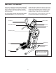
www.proform.com Model No. PFEL09915.0 Serial No. Write the serial number in the space above for reference. Serial Number Decal ACTIVATE YOUR WARRANTY To register your product and activate your warranty today, go to www.proformservice.com/ registration. CUSTOMER CARE For service at any time, go to www.proformservice.com. Or call 1-888-533-1333 Mon.–Fri. 6 a.m.–6 p.m. MT Sat. 8 a.m.–12 p.m. MT Please do not contact the store.
TABLE OF CONTENTS WARNING DECAL PLACEMENT . . . . . . . . . . . . . . . . . . . . . . . . . . . . . . . . . . . . . . . . . . . . . . . . . . . . . . . . . . . . . . .2 IMPORTANT PRECAUTIONS. . . . . . . . . . . . . . . . . . . . . . . . . . . . . . . . . . . . . . . . . . . . . . . . . . . . . . . . . . . . . . . . . . 3 BEFORE YOU BEGIN. . . . . . . . . . . . . . . . . . . . . . . . . . . . . . . . . . . . . . . . . . . . . . . . . . . . . . . . . . . . . . . . . . . . . . . .5 PART IDENTIFICATION CHART.
IMPORTANT PRECAUTIONS WARNING: To reduce the risk of serious injury, read all important precautions and instructions in this manual and all warnings on the trainer before using the trainer. ICON assumes no responsibility for personal injury or property damage sustained by or through the use of this product. 1. It is the responsibility of the owner to ensure that all users of the trainer are adequately informed of all precautions. 9. Keep children under age 13 and pets away from the trainer at all times.
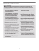
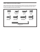
UTS STANDARD SERVICE PLANS all 4
BEFORE YOU BEGIN Thank you for selecting the revolutionary PROFORM® CARDIO HIIT TRAINER. The CARDIO HIIT TRAINER trainer provides an impressive selection of features designed to make your workouts at home more effective and enjoyable. reading this manual, please see the front cover of this manual. To help us assist you, note the product model number and serial number before contacting us. The model number and the location of the serial number decal are shown on the front cover of this manual.
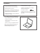
PART IDENTIFICATION CHART Use the drawings below to identify the small parts needed for assembly. The number in parentheses below each drawing is the key number of the part, from the PART LIST near the end of this manual. The number following the key number is the quantity needed for assembly. Note: If a part is not in the hardware kit, check to see if it has been preassembled. Extra parts may be included.
ASSEMBLY • To hire an authorized service technician to assemble this product, call 1-800-445-2480. • To identify small parts, see page 6. • In addition to the included tool(s), assembly requires the following tools: • Assembly requires two persons. one Phillips screwdriver • Place all parts in a cleared area and remove the packing materials. Do not dispose of the packing materials until you finish all assembly steps. Assembly may be easier if you have your own set of wrenches.
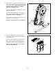
2. With the help of a second person, place some of the packing materials (not shown) under the right side of the Frame (1). Have the second person hold the Frame to prevent it from tipping while you complete this step. 2 Identify the Right and Left Stabilizers (8, 9) and orient them as shown. Attach the Right Stabilizer (8) to the Frame (1) with four M10 x 20mm Screws (110); start all the Screws, and then tighten them. Then, remove the packing materials from under the right side of the Frame (1).
4. Attach the Right Pedal Base (2) to the Right Pedal Leg (24) with four M8 x 20mm Screws (102); start all the Screws, and then tighten them. 4 Attach the Left Pedal Base (not shown) to the Left Pedal Leg (not shown) in the same way. 102 24 102 2 5. Press the Rear Cover (53) onto the Left and Right Shields (50, 51). 5 18 Attach Rear Cover (53) with four M4 x 16mm Flat Head Screws (101); start all the Flat Head Screws, and then tighten them.
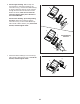
6. See the upper drawing. With the help of a second person, orient the Console (5), the Console Cover (7), and the Console Bracket (4) as shown. Route the wires (A) on the Console through the Console Cover and the Console Bracket as shown; make sure to insert the wires through the upper part of the hole in the Console Bracket. 6 5 7 See the lower drawing. Tip: Avoid pinching the wires.
8. While a second person holds the Console Bracket (4) near the Frame (1), connect the wires on the Console to the Main Wire (115) and to the Pulse Wire (117). 8 Avoid pinching the wires Tip: Avoid pinching the wires. Attach the Console Bracket (4) to the Frame (1) with two M8 x 86mm Screws (109) and two M8 x 15mm Screws (96); start all the Screws, and then tighten them. 117 109 4 96 115 96 1 9. Identify the Right and Left Handlebars (10, 11). 9 Make sure that the Pedals (not shown) are level.
10. Identify the Rear and Front Pivot Covers (65, 66). 10 Press a set of Rear and Front Pivot Covers (65, 66) together around the Right Handlebar (10) near the bend (A). Then, attach them to each other with two M4 x 22mm Screws (107). 10 See the inset drawing. Slide the Rear and Front Pivot Covers (65, 66) toward the Shield Cover (12). Attach the Front Pivot Cover to the Right Handlebar (10) with an M4 x 22mm Screw (107). 66 65 A Repeat this step on the other side of the trainer. 65 10 11.
12. Plug the Power Adapter (118) into the receptacle on the frame of the trainer. 12 118 Note: To plug the Power Adapter (118) into an outlet, see HOW TO PLUG IN THE POWER ADAPTER on page 14. 13. Make sure that all parts are properly tightened before you use the trainer. Extra parts may be included. Place a mat beneath the trainer to protect the floor.
HOW TO USE THE TRAINER HOW TO PLUG IN THE POWER ADAPTER HOW TO MOVE THE TRAINER IMPORTANT: If the trainer has been exposed to cold temperatures, allow it to warm to room temperature before you plug in the power adapter. If you do not do this, you may damage the console displays or other electronic components. Due to the size and weight of the trainer, moving it requires two persons. Stand in front of the trainer, hold the console bracket, and place one foot against one of the wheels.
HOW TO EXERCISE ON THE TRAINER HOW TO LEVEL THE TRAINER To mount the trainer, hold the handlebars or the pulse grips and step onto the pedal that is in the lower position. Then, step onto the other pedal. Push the pedals until they begin to move with a continuous motion. Note: The pedals can turn in either direction. It is recommended that you turn the pedals in the direction shown by the arrow; however, for variety, you can turn the pedals in the opposite direction.
CONSOLE DIAGRAM FEATURES OF THE CONSOLE The advanced console offers an array of features designed to make your workouts more effective and enjoyable. When you use the manual mode, you can change the resistance of the pedals with the touch of a button. As you exercise, the console will provide continuous exercise feedback. You can even measure your heart rate using the handgrip heart rate monitor or a compatible heart rate monitor.
HOW TO USE THE MANUAL MODE Calories (Cals.)—When the manual mode is selected, this display mode will show the approximate number of calories you have burned. When a workout is selected, this display mode will show either the approximate number of calories remaining to be burned or the approximate number of calories you have burned. 1. Turn on the console. Begin pedaling or press any button on the console to turn on the console.
y Trail—This tab will show a track that represents M 1/4 mile (400 m). As you exercise, the flashing rectangle will show your progress. The My Trail tab will also show the number of laps you complete. If there are sheets of plastic on the metal contacts on the handgrip heart rate monitor, remove the plastic. To measure your heart rate, Contacts hold the handgrip heart rate monitor with your palms resting against the contacts. Avoid moving your hands or gripping the contacts tightly.
HOW TO USE AN ONBOARD WORKOUT At the end of each segment of the workout, a series of tones will sound and the next segment of the profile will begin to flash. 1. Turn on the console. Begin pedaling or press any button on the console to turn on the console. If a different resistance level is programmed for the next segment, the resistance level will appear in the display and the resistance level will change.
4. Follow your progress with the display. THE OPTIONAL CHEST HEART RATE MONITOR See step 4 on page 17. Whether your goal is to burn fat or to strengthen your cardiovascular system, the key to achieving the best results is to maintain the proper heart rate during your workouts. The optional chest heart rate monitor will enable you to continuously monitor your heart rate while you exercise, helping you to reach your personal fitness goals.
HOW TO CONNECT YOUR SMART DEVICE TO THE CONSOLE HOW TO CONNECT YOUR HEART RATE MONITOR TO THE CONSOLE The console supports BLUETOOTH connections to smart devices via the iFit app and to compatible heart rate monitors. Note: Other BLUETOOTH connections are not supported. The console is compatible with all BLUETOOTH Smart heart rate monitors. To connect your BLUETOOTH Smart heart rate monitor to the console, press the Bluetooth Smart button on the console.
HOW TO CHANGE CONSOLE SETTINGS 3. Change settings as desired. 1. Select the settings mode. Units—The currently selected unit of measurement will appear in the display. To change the unit of measurement, press the Enter button repeatedly. To view distance in miles, select ENGLISH. To view distance in kilometers, select METRIC. To select the settings mode, press the gear button. The settings information will appear in the display.
FCC INFORMATION This equipment has been tested and found to comply with the limits for a Class B digital device, pursuant to part 15 of the FCC Rules. These limits are designed to provide reasonable protection against harmful interference in a residential installation. This equipment generates, uses, and can radiate radio frequency energy and, if not installed and used in accordance with the instructions, may cause harmful interference to radio communications.
MAINTENANCE AND TROUBLESHOOTING MAINTENANCE HOW TO ADJUST THE REED SWITCH Regular maintenance is important for optimal performance and to reduce wear. Inspect and properly tighten all parts each time the trainer is used. Replace any worn parts immediately. If the console does not display correct feedback, the reed switch should be adjusted. To adjust the reed switch, first unplug the power adapter. Next, remove the four indicated M4 x 16mm Flat Head Screws (101) and the Lower Rear Shield Cover (68).
HOW TO ADJUST THE DRIVE BELT Then, locate the lower Adjustment Screw (A). Tighten the lower Adjustment Screw four turns; this will tighten the Large Drive Belt (31). If the pedals slip while you are pedaling, even while the resistance is adjusted to the highest level, the drive belts may need to be adjusted. To adjust the drive belts, first unplug the power adapter. Next, remove the four indicated M4 x 16mm Flat Head Screws (101) and the Lower Rear Shield Cover (68).
EXERCISE GUIDELINES Burning Fat—To burn fat effectively, you must exercise at a low intensity level for a sustained period of time. During the first few minutes of exercise, your body uses carbohydrate calories for energy. Only after the first few minutes of exercise does your body begin to use stored fat calories for energy. If your goal is to burn fat, adjust the intensity of your exercise until your heart rate is near the lowest number in your training zone.
SUGGESTED STRETCHES The correct form for several basic stretches is shown at the right. Move slowly as you stretch; never bounce. 1. Toe Touch Stretch Stand with your knees bent slightly and slowly bend forward from your hips. Allow your back and shoulders to relax as you reach down toward your toes as far as possible. Hold for 15 counts, then relax. Repeat 3 times. Stretches: Hamstrings, back of knees and back. 1 2. Hamstring Stretch Sit with one leg extended.
PART LIST Key No. Qty. 1 2 3 4 5 6 7 8 9 10 11 12 13 14 15 16 17 18 19 20 21 22 23 24 25 26 27 28 29 30 31 32 33 34 35 36 37 38 39 40 41 42 43 44 45 46 47 48 49 50 1 1 1 1 1 1 1 1 1 1 1 1 2 1 1 1 2 1 1 1 1 1 1 1 1 2 1 1 2 1 1 2 2 1 2 1 1 1 1 1 1 1 3 2 2 1 1 1 2 1 Model No. PFEL09915.0 R0316B Description Key No. Qty.
Key No. Qty. 101 102 103 104 105 106 107 108 109 110 111 112 113 114 14 8 18 2 6 14 10 8 2 8 4 1 25 15 Description Key No. Qty.
77 71 108 120 23 87 84 73 108 79 35 79 3 102 87 84 71 91 73 78 70 87 88 30 89 31 29 78 108 76 70 96 2 113 70 75 95 95 72 1 42 43 27 30 17 41 21 121 74 43 94 14 22 87 25 90 32 70 93 85 33 78 120 119 85 70 92 26 73 116 72 70 74 29 89 90 100 100 17 7 85 71 93 73 91 119 92 19 79 84 24 35 124 71 73 16 113 4 122 102 94 106 28 87 38 36 78 80 99 97 39 20 70 86 37 43 40 75 76 123 70 70 15 96 109 80 5 77 87 70 34 70 1
101 31 53 83 113 54 101 55 18 83 114 101 114 69 83 103 101 106 56 114 44 9 99 113 68 106 49 101 113 81 113 46 113 55 83 103 113 103 57 56 103 103 114 114 45 101 48 60 113 83 83 61 83 113 82 69 82 113 83 101 59 113 50 105 67 8 82 56 110 113 106 113 81 106 56 99 57 115 113 103 47 59 103 63 107 49 104 58 103 113 65 66 113 82 101 11 106 51 65 52 104 62 117 103 44 10 118 105 67 64 60 107 66 106 EXPLODED DRAWI
ORDERING REPLACEMENT PARTS To order replacement parts, please see the front cover of this manual.