www.proform.com Model No. PFEL06916.0 Serial No. Write the serial number in the space above for reference. Serial Number Decal ACTIVATE YOUR WARRANTY To register your product and activate your warranty today, go to www.proformservice.com/ registration. CUSTOMER CARE For service at any time, go to www.proformservice.com. Or call 1-888-533-1333 Mon.–Fri. 6 a.m.–6 p.m. MT Sat. 8 a.m.–12 p.m. MT Please do not contact the store.
TABLE OF CONTENTS WARNING DECAL PLACEMENT . . . . . . . . . . . . . . . . . . . . . . . . . . . . . . . . . . . . . . . . . . . . . . . . . . . . . . . . . . . . . . .2 IMPORTANT PRECAUTIONS. . . . . . . . . . . . . . . . . . . . . . . . . . . . . . . . . . . . . . . . . . . . . . . . . . . . . . . . . . . . . . . . . . 3 BEFORE YOU BEGIN. . . . . . . . . . . . . . . . . . . . . . . . . . . . . . . . . . . . . . . . . . . . . . . . . . . . . . . . . . . . . . . . . . . . . . . .6 ASSEMBLY . . . . . . . . .
IMPORTANT PRECAUTIONS WARNING: To reduce the risk of burns, fire, electric shock, or injury to persons, read all important precautions and instructions in this manual and all warnings on your elliptical before using your elliptical. ICON assumes no responsibility for personal injury or property damage sustained by or through the use of this product. 1. It is the responsibility of the owner to ensure that all users of the elliptical are adequately informed of all precautions. 10.
18. The heart rate monitor is not a medical device. Various factors may affect the accuracy of heart rate readings. The heart rate monitor is intended only as an exercise aid in determining heart rate trends in general. 20. Keep your back straight while using the elliptical; do not arch your back. 21. Over exercising may result in serious injury or death. If you feel faint, if you become short of breath, or if you experience pain while exercising, stop immediately and cool down. 19.
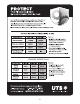
STANDARD SERVICE PLANS all 5
BEFORE YOU BEGIN Thank you for selecting the revolutionary PROFORM® SMART STRIDER 695 CSE elliptical. The SMART STRIDER 695 CSE elliptical provides an impressive selection of features designed to make your workouts at home more effective and enjoyable. reading this manual, please see the front cover of this manual. To help us assist you, note the product model number and serial number before contacting us.
ASSEMBLY • To hire an authorized service technician to assemble this product, call 1-800-445-2480. • In addition to the included tool(s), assembly requires the following tool(s): • Assembly requires two persons. one Phillips screwdriver • Place all parts in a cleared area and remove the packing materials. Do not dispose of the packing materials until you finish all assembly steps. Assembly may be easier if you have a set of wrenches. To avoid damaging parts, do not use power tools. 1. G o to www.
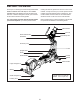
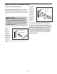
3. With the help of another person, place some sturdy packing materials under the front of the Frame (1). Have the other person hold the elliptical to prevent it from tipping. 3 84 73 If there are shipping supports attached to the front of the Frame (1), remove the screws attaching the shipping supports. Discard the screws and the shipping supports. Attach the Front Stabilizer (73) to the Frame (1) with two M10 x 120mm Screws (84). 1 Then, remove the packing materials and lower the elliptical. 4.
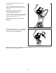
5. Rotate the Right Upper Body Arm (9) to the position shown. 5 Attach the Right Upper Body Arm (9) to the Right Upper Body Leg (6) with an M10 x 50mm Screw (95). IMPORTANT: Tighten the indicated M10 x 45mm Hex Screw (78). 9 20 78 Press the Upper Body Arm Cover (20) downward and turn it so that it is flush with the Right Leg Front and Rear Covers (11, 15). 11, 15 Repeat this step on the other side of the elliptical. 95 6.
HOW TO USE THE ELLIPTICAL HOW TO PLUG IN THE POWER CORD A temporary adapter may be used to connect the power cord to a 2-pole receptacle as shown at the right if a properly grounded outlet is not available. This product must be grounded. If it should malfunction or break down, grounding provides a path of least resistance for electric current to reduce the risk of electric shock. The power cord has a plug with a grounding pin.
HOW TO MOVE THE ELLIPTICAL HOW TO ADJUST THE POSITIONS OF THE PEDALS Due to the size and weight of the elliptical, moving it requires two persons. First, loosen the upright knob. Next, pull the upright knob, pull the upright backward until the latch stops the upright, and then release the upright knob. Next, pull the upright forward slightly, lift the latch, and then lower the upright to the folded position.
HOW TO EXERCISE ON THE ELLIPTICAL See HOW TO MOVE THE ELLIPTICAL on page 11 and lower the upright to the folded position. To mount the elliptical, hold the handlebars or the upper body arms and step onto the pedal that is in the lower position. Then, step onto the other pedal. Push the pedals until they begin to move with a continuous motion. Note: The pedals can turn in either direction.
CONSOLE DIAGRAM FEATURES OF THE CONSOLE The advanced console offers an array of features designed to make your workouts more effective and enjoyable. When you use the manual mode of the console, you can change the resistance of the pedals with the touch of a button. You can also create custom manual workouts with alternating high- and low-intensity intervals. As you exercise, the console will provide continuous exercise feedback.
HOW TO TURN ON THE POWER HOW TO USE THE MANUAL MODE IMPORTANT: If the elliptical has been exposed to cold temperatures, allow it to warm to room temperature before you turn on the power. If you do not do this, you may damage the console displays or other electrical components. 1. Begin pedaling or press any button on the console to turn on the console. Plug in the power cord (see HOW TO PLUG IN THE POWER CORD on page 10). Next, locate the power switch on the frame near the power cord.
To vary the motion of the pedals, you can change the incline of the frame. To change the incline, press the Incline increase and decrease buttons. To set a power output target, press the Watts increase and decrease buttons until the desired power output target appears in the display. Note: After you press a button, it will take a moment for the frame to reach the selected incline level. Note: After you set a power output target, the resistance level will automatically adjust to a preset level.
7. Follow your progress with the display. Change the volume level of the console by pressing the Vol increase and decrease buttons. The display can show the following workout information: Calories (CALS)—The approximate number of calories you have burned. To pause the console, simply stop pedaling. When the console is paused, the time will flash in the display. To continue your workout, simply resume pedaling. Distance (MI or KI)—The distance that you have pedaled in miles or kilometers.
10. When you are finished exercising, unplug the power cord. When your pulse is detected, your heart rate will be shown in the display. For the most accurate heart rate reading, hold the contacts for at least 15 seconds. If the pedals do not move for several seconds, a series of tones will sound, the console will pause, and the display will pause. If the display does not show your heart rate, make sure that your hands are positioned as described.
HOW TO USE AN ONBOARD WORKOUT At the end of each segment of the workout, a series of tones will sound. The resistance level for the next segment will appear in the display for a few seconds to alert you. The resistance of the pedals will then change. 1. Begin pedaling or press any button on the console to turn on the console. See HOW TO TURN ON THE POWER on page 14. he power ring will show a flashing indicator that T represents the power output target for the segment.
5. Follow your progress with the display. THE OPTIONAL CHEST HEART RATE MONITOR See step 7 on page 16. Whether your goal is to burn fat or to strengthen your cardiovascular system, the key to achieving the best results is to maintain the proper heart rate during your workouts. The optional chest heart rate monitor will enable you to continuously monitor your heart rate while you exercise, helping you to reach your personal fitness goals.
HOW TO CONNECT YOUR TABLET TO THE CONSOLE 5. Disconnect your tablet from the console if desired. The console supports BLUETOOTH connections to tablets via the iFit Bluetooth Tablet app and to compatible heart rate monitors. Note: Other BLUETOOTH connections are not supported. To disconnect your tablet from the console, first select the disconnect option in the iFit Bluetooth Tablet app. Then, press and hold the iFit Sync button on the console until the LED on the console turns solid green. 1.
THE SETTINGS MODE Press the Tempo Apps button repeatedly until the console usage information appears in the display. The console features a settings mode that allows you to select a unit of measurement for the console and to view console usage information. The display will alternate showing the total time (in hours) that the console has been used since the elliptical was purchased and the total distance (in miles or kilometers) that the elliptical has been pedaled.
MAINTENANCE AND TROUBLESHOOTING MAINTENANCE HOW TO CALIBRATE THE INCLINE SYSTEM Regular maintenance is important for optimal performance and to reduce wear. Inspect and properly tighten all parts each time the elliptical is used. Replace any worn parts immediately. If the incline system is not functioning properly, it may need to be calibrated. To calibrate the incline system, press and hold the Manual Control button for several seconds until the test mode appears in the display.
HOW TO ADJUST THE REED SWITCH If the console does not display correct feedback, the reed switch should be adjusted. To adjust the reed switch, first press the power switch to the off position and unplug the power cord. 61 41 58 Next, remove the four M4 x 16mm 37 Screws (not shown) from the Large Storage 27 Foot (27), and then remove the Large Storage Foot.
HOW TO ADJUST THE DRIVE BELT Next, remove the four M4 x 16mm Screws (not shown) from the Large Storage Foot (27), and then remove the Large Storage Foot. Remove the two M4 x 16mm Screws (not shown) from the Top Shield (37), and use a standard screwdriver to pry the Top Shield upward off the elliptical. Then, pry the left Pedal Disc (36) off the elliptical. If the pedals slip while you are pedaling, even while the resistance is adjusted to the highest setting, the drive belt may need to be adjusted.
EXERCISE GUIDELINES Burning Fat—To burn fat effectively, you must exercise at a low intensity level for a sustained period of time. During the first few minutes of exercise, your body uses carbohydrate calories for energy. Only after the first few minutes of exercise does your body begin to use stored fat calories for energy. If your goal is to burn fat, adjust the intensity of your exercise until your heart rate is near the lowest number in your training zone.
SUGGESTED STRETCHES The correct form for several basic stretches is shown at the right. Move slowly as you stretch; never bounce. 1. Toe Touch Stretch Stand with your knees bent slightly and slowly bend forward from your hips. Allow your back and shoulders to relax as you reach down toward your toes as far as possible. Hold for 15 counts, then relax. Repeat 3 times. Stretches: Hamstrings, back of knees and back. 1 2. Hamstring Stretch Sit with one leg extended.
PART LIST Key No. Qty. 1 2 3 4 5 6 7 8 9 10 11 12 13 14 15 16 17 18 19 20 21 22 23 24 25 26 27 28 29 30 31 32 33 34 35 36 37 38 39 40 41 42 43 44 45 46 47 48 49 50 1 1 1 1 1 1 1 1 1 2 1 1 1 1 1 1 6 1 1 2 1 1 4 1 2 2 1 1 4 2 2 1 10 1 1 2 1 2 1 1 2 1 2 1 1 1 2 4 1 2 Model No. PFEL06916.0 R1016A Description Key No. Qty.
Key No. Qty. 101 102 103 104 105 106 107 108 109 110 111 112 113 114 115 116 117 1 1 4 1 1 1 1 1 2 4 1 2 14 1 1 2 2 Description Key No. Qty.
71 29 84 70 66 107 60 53 43 74 79 61 51 106 115 61 97 41 103 99 68 91 96 103 99 100 41 25 130 82 98 38 24 50 77 72 47 61 99 57 46 56 52 61 48 54 71 40 79 38 58 7 4 99 82 60 25 1 112 81 61 43 55 42 74 17 55 28 129 102 61 83 17 61 33 59 110 131 129 61 83 104 129 73 98 108 59 118 75 98 61 105 33 125 84 75 81 112 114 61 98 48 77 109 84 EXPLODED DRAWING A Model No. PFEL06916.
61 30 87 85 3 81 63 69 80 88 62 2 61 94 89 61 61 86 90 122 120 67 63 93 61 14 124 12 21 5 8 16 10 29 92 101 19 18 127 39 29 20 33 98 121 116 30 75 81 61 20 128 126 75 13 95 9 61 32 49 117 31 23 61 76 123 33 119 15 17 61 10 23 33 61 76 6 78 17 22 76 33 11 EXPLODED DRAWING B Model No. PFEL06916.
26 113 61 27 113 61 61 64 61 36 64 113 44 113 64 61 61 65 61 37 64 45 65 31 64 113 64 34 65 65 113 65 113 61 36 111 61 113 65 26 61 61 35 65 61 61 132 EXPLODED DRAWING C Model No. PFEL06916.
ORDERING REPLACEMENT PARTS To order replacement parts, see the front cover of this manual.