www.proform.com Model No. PFEL02915.0 Serial No. Write the serial number in the space above for reference. Serial Number Decal (under frame) ACTIVATE YOUR WARRANTY To register your product and activate your warranty today, go to www.proformservice.com/ registration. CUSTOMER CARE For service at any time, go to www.proformservice.com. Or call 1-888-533-1333 Mon.–Fri. 6 a.m.–6 p.m. MT Sat. 8 a.m.–12 p.m. MT Please do not contact the store.
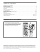
TABLE OF CONTENTS WARNING DECAL PLACEMENT . . . . . . . . . . . . . . . . . . . . . . . . . . . . . . . . . . . . . . . . . . . . . . . . . . . . . . . . . . . . . . .2 IMPORTANT PRECAUTIONS. . . . . . . . . . . . . . . . . . . . . . . . . . . . . . . . . . . . . . . . . . . . . . . . . . . . . . . . . . . . . . . . . . 3 BEFORE YOU BEGIN. . . . . . . . . . . . . . . . . . . . . . . . . . . . . . . . . . . . . . . . . . . . . . . . . . . . . . . . . . . . . . . . . . . . . . . .5 PART IDENTIFICATION CHART.
IMPORTANT PRECAUTIONS WARNING: To reduce the risk of serious injury, read all important precautions and instructions in this manual and all warnings on your elliptical before using your elliptical. ICON assumes no responsibility for personal injury or property damage sustained by or through the use of this product. 1. It is the responsibility of the owner to ensure that all users of the elliptical are adequately informed of all precautions. 9.
STANDARD SERVICE PLANS all 4
BEFORE YOU BEGIN Thank you for selecting the new PROFORM® 225 CSE elliptical. The 225 CSE elliptical provides a selection of features designed to make your workouts at home more effective and enjoyable. manual. To help us assist you, note the product model number and serial number before contacting us. The model number and the location of the serial number decal are shown on the front cover of this manual. For your benefit, read this manual carefully before you use the elliptical.
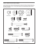
PART IDENTIFICATION CHART Use the drawings below to identify the small parts needed for assembly. The number in parentheses below each drawing is the key number of the part, from the PART LIST near the end of this manual. The number following the key number is the quantity needed for assembly. Note: If a part is not in the hardware kit, check to see if it has been preassembled.
ASSEMBLY • To hire an authorized service technician to assemble this product, call 1-800-445-2480. • In addition to the included tool(s), assembly requires the following tools: • Assembly requires two persons. one adjustable wrench • Place all parts in a cleared area and remove the packing materials. Do not dispose of the packing materials until you finish all assembly steps. one Phillips screwdriver • Left and right parts are marked “L” or “Left” and “R” or “Right.
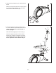
3. Orient the Rear Stabilizer (9) as indicated by the sticker. 3 While a second person lifts the rear of the Frame (1), attach the Rear Stabilizer (9) to the Frame with two M10 x 68mm Screws (34). 9 1 34 4. Orient the Upright (2) and the Top Shield (41) as shown. Slide the Top Shield upward onto the Upright. Do not remove the wire ties (B, C) from the Upright. 4 B C Next, slide the Upright (2) onto the Frame (1).
5. See the inset drawing. Locate the wire tie (C) in the lower end of the Upright (2). Tie the wire tie to the Wire Harness (73). Next, pull the upper end of the wire tie until the Wire Harness is routed through the Upright. 5 Tip: To prevent the Wire Harness (73) from falling into the Upright (2), secure the Wire Harness with the wire tie (C). 29 Next, slide the Top Shield (41) downward to the Frame (1). Do not press the Top Shield into place yet.
7. The Console (23) can use four AA batteries (not included); alkaline batteries are recommended. Do not use old and new batteries together or alkaline, standard, and rechargeable batteries together. IMPORTANT: If the Console has been exposed to cold temperatures, allow it to warm to room temperature before you insert batteries. Otherwise, you may damage the console displays or other electronic components.
9. Insert the excess wire into the Upright (2) or into the Console (23). 9 23 Avoid pinching the wires Press the Rear Upright Cover (75) into the Upright (2). Have a second person hold the Rear Upright Cover in place. 2 Tip: Avoid pinching the wires. Attach the Console (23) to the Upright (2) with four M4 x 16mm Screws (52); start all the Screws, and then tighten them. 75 52 10.
. Identify the Right Upper Body Arm (8). 12 Slide an Upper Body Arm Cover (42) upward onto the Right Upper Body Arm (8). 6 Next, insert the Right Upper Body Arm (8) into an Upper Body Leg (5). Tip: Have a second person hold the Upper Body Arm Cover (42) while you perform this action: 8 Attach the Right Upper Body Arm (8) to the Upper Body Leg (5) with three M8 x 41mm Bolts (50) and three M8 Jam Nuts (38). Make sure that the Jam Nuts are inside the hexagonal holes (E).
14. Orient an Upper Body Arm Spacer (47) as shown. Slide the Upper Body Arm Spacer onto the right side of the Pivot Axle (26). 14 Next, slide the Right Upper Body Arm (8) onto the right side of the Pivot Axle (26). Repeat these actions on the other side of the elliptical. 6 26 Tighten an M8 x 25mm Screw (56) with an M8 Washer (55) into each end of the Pivot Axle (26) at the same time. 47 8 42 Next, slide the right Upper Body Arm Cover (42) upward.
16. Apply a small amount of grease to the axle on the Right Crank Arm (80). 16 Slide the Right Pedal Arm (12) onto the axle on the Right Crank Arm (80). Next, slide an M10 x 28mm Washer (83) onto an M10 x 20mm Screw (40), and tighten the Screw into the axle. Then, press a Pedal Arm Cap (74) into the Right Pedal Arm (12). Grease Repeat this step on the other side of the elliptical. 12 80 83 17. See assembly steps 4 and 5. Tighten the M10 x 20mm Screws (40) and the M10 x 77mm Bolt (7).
18. Attach the Tablet Holder (32) to the back of the Console (23) with four M4 x 16mm Screws (52); start all the Screws, and then tighten them. 18 23 32 52 19. Make sure that all parts of the elliptical are properly tightened. Extra parts may be included. To protect the floor or carpet from damage, place a mat under the elliptical.
HOW TO USE THE ELLIPTICAL HOW TO MOVE THE ELLIPTICAL HOW TO EXERCISE ON THE ELLIPTICAL Due to the size and weight of the elliptical, moving it requires two persons. Stand in front of the elliptical, hold the upright, and place one foot against one of the front wheels. Pull on the upright and have a second person lift the rear stabilizer until the elliptical will roll on the wheels. Carefully move the elliptical to the desired location, and then lower it to the floor.
HOW TO LEVEL THE ELLIPTICAL HOW TO USE THE TABLET HOLDER If the elliptical rocks slightly on your floor during use, turn one or both of the leveling feet beneath the rear stabilizer until the rocking motion is eliminated. IMPORTANT: The tablet holder was designed for use with most full-size tablets and smart phones. Do not place any other electronic device or object into the tablet holder.
CONSOLE DIAGRAM FEATURES OF THE CONSOLE The advanced console offers an array of features designed to make your workouts more effective and enjoyable. When you use the manual mode of the console, you can change the resistance of the pedals with the touch of a button. As you pedal, the console will provide continuous exercise feedback. You can even measure your heart rate using the handgrip heart rate monitor or a compatible heart rate monitor.
HOW TO USE THE MANUAL MODE The upper display—This display will show your pedaling speed in revolutions per minute (RPM) and your power output in watts. The display will change every few seconds. 1. Turn on the console. Press any button or begin pedaling to turn on the console. This display will also show the resistance level of the pedals for a few seconds each time the resistance level changes.
5. Measure your heart rate if desired. When your pulse is detected, your heart rate will be shown in the upper display. For the most accurate heart rate reading, hold the contacts for at least 15 seconds. You can measure your heart rate using either the handgrip heart rate monitor or a compatible heart rate monitor. For information about purchasing an optional chest heart rate monitor, see page 23. If your heart rate is not shown, make sure that your hands are positioned as described.
HOW TO USE A QUICK ONBOARD WORKOUT As you exercise, keep your pedaling speed within the target speed zone for the current segment by increasing or decreasing your pedaling speed or by increasing or decreasing the resistance of the pedals. 1. Turn on the console. Press any button or begin pedaling to turn on the console. IMPORTANT: The target speed is intended only to provide motivation. Make sure to pedal at a speed and a resistance level that is comfortable for you.
HOW TO CONNECT YOUR TABLET TO THE CONSOLE 5. Disconnect your tablet from the console if desired. The console supports BLUETOOTH connections to tablets via the iFit Bluetooth Tablet app and to compatible heart rate monitors. Note: Other BLUETOOTH connections are not supported. To disconnect your tablet from the console, first select the disconnect option in the iFit Bluetooth Tablet app. Then, press and hold the iFit Sync button on the console until the LED on the console turns solid green. 1.
THE OPTIONAL CHEST HEART RATE MONITOR To select the settings mode, press and hold down the On/Reset button until the settings mode information appears in the display. Whether your goal is to burn fat or to strengthen your cardiovascular system, the key to achieving the best results is to maintain the proper heart rate during your workouts. The optional chest heart rate monitor will enable you to continuously monitor your heart rate while you exercise, helping you to reach your personal fitness goals.
MAINTENANCE AND TROUBLESHOOTING MAINTENANCE Note: For clarity, the right pedal disc is not shown in the drawing below. Regular maintenance is important for optimal performance and to reduce wear. Inspect and properly tighten all parts each time the elliptical is used. Replace any worn parts immediately. Locate the Reed Switch (53). Loosen, but do not remove, the M4 x 16mm Screw (52). To clean the elliptical, use a damp cloth and a small amount of mild dish soap.
HOW TO ADJUST THE DRIVE BELT Loosen the M8 x 22mm Screw (65), and turn the M10 x 60mm Bolt (62) until the Drive Belt (19) is tight. If you can feel the pedals slip while you are pedaling, even when the resistance is adjusted to the highest level, the drive belt may need to be adjusted. To adjust the drive belt, you must remove the pedal arms, the pedal discs, and the left shield. First, see step 17 on page 14 and step 16 on page 14 and remove the Left and Right Pedal Arms (11, 12).
EXERCISE GUIDELINES Burning Fat—To burn fat effectively, you must exercise at a low intensity level for a sustained period of time. During the first few minutes of exercise, your body uses carbohydrate calories for energy. Only after the first few minutes of exercise does your body begin to use stored fat calories for energy. If your goal is to burn fat, adjust the intensity of your exercise until your heart rate is near the lowest number in your training zone.
SUGGESTED STRETCHES The correct form for several basic stretches is shown at the right. Move slowly as you stretch; never bounce. 1. Toe Touch Stretch Stand with your knees bent slightly and slowly bend forward from your hips. Allow your back and shoulders to relax as you reach down toward your toes as far as possible. Hold for 15 counts, then relax. Repeat 3 times. Stretches: Hamstrings, back of knees and back. 1 2. Hamstring Stretch Sit with one leg extended.
NOTES 28
PART LIST Key No. Qty. 1 2 3 4 5 6 7 8 9 10 11 12 13 14 15 16 17 18 19 20 21 22 23 24 25 26 27 28 29 30 31 32 33 34 35 36 37 38 39 40 41 42 43 44 45 46 1 1 1 1 2 1 1 1 1 1 1 1 1 1 2 1 1 1 1 2 2 1 1 2 2 1 6 1 1 1 2 1 1 4 1 2 2 8 2 6 1 2 2 2 1 2 Model No. PFEL02915.0 R1016A Description Key No. Qty.
EXPLODED DRAWING A 24 Model No. PFEL02915.
EXPLODED DRAWING B 13 74 40 83 Model No. PFEL02915.
ORDERING REPLACEMENT PARTS To order replacement parts, please see the front cover of this manual.