Model No. PETL79816.0 Serial No. Write the serial number in the space above for reference. USER’S MANUAL Serial Number Decal CUSTOMER SERVICE UNITED KINGDOM Call: 0330 123 1045 From Ireland: 053 92 36102 Website: www.iconsupport.eu E-mail: csuk@iconeurope.com Write: ICON Health & Fitness, Ltd. Unit 1D, The Gateway Fryers Way, Silkwood Park OSSETT WF5 9TJ UNITED KINGDOM AUSTRALIA Call: 1800 993 770 E-mail: australiacc@iconfitness.
TABLE OF CONTENTS WARNING DECAL PLACEMENT . . . . . . . . . . . . . . . . . . . . . . . . . . . . . . . . . . . . . . . . . . . . . . . . . . . . . . . . . . . . . . .2 IMPORTANT PRECAUTIONS. . . . . . . . . . . . . . . . . . . . . . . . . . . . . . . . . . . . . . . . . . . . . . . . . . . . . . . . . . . . . . . . . . 3 BEFORE YOU BEGIN. . . . . . . . . . . . . . . . . . . . . . . . . . . . . . . . . . . . . . . . . . . . . . . . . . . . . . . . . . . . . . . . . . . . . . . .5 PART IDENTIFICATION CHART.
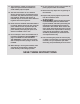
IMPORTANT PRECAUTIONS WARNING: To reduce the risk of burns, fire, electric shock, or injury to persons, read all important precautions and instructions in this manual and all warnings on your treadmill before using your treadmill. ICON assumes no responsibility for personal injury or property damage sustained by or through the use of this product. 1. It is the responsibility of the owner to ensure that all users of this treadmill are adequately informed of all warnings and precautions. 12.
21. The treadmill is capable of high speeds. Adjust the speed in small increments to avoid sudden jumps in speed. 26. Do not change the incline of the treadmill by placing objects under the treadmill. 27. Never insert any object into any opening on the treadmill. 22. The heart rate monitor is not a medical device. Various factors, including the user’s movement, may affect the accuracy of heart rate readings.
BEFORE YOU BEGIN Thank you for selecting the new PROFORM® PERFORMANCE 400I treadmill. The PERFORMANCE 400I treadmill provides an impressive selection of features designed to make your workouts at home more effective and enjoyable. reading this manual, please see the front cover of this manual. To help us assist you, note the product model number and serial number before contacting us. The model number and the location of the serial number decal are shown on the front cover of this manual.
PART IDENTIFICATION CHART Use the drawings below to identify small parts used for assembly. The number in parentheses below each drawing is the key number of the part, from the PART LIST near the end of this manual. The number following the key number is the quantity used for assembly. Note: If a part is not in the hardware kit, check to see whether it is preattached. Extra parts may be included.
ASSEMBLY • Assembly requires two persons. • Left parts are marked “L” or “Left” and right parts are marked “R” or “Right.” • Place all parts in a cleared area and remove the packing materials. Do not dispose of the packing materials until you finish all assembly steps. • To identify small parts, see page 6. • Assembly requires the following tools: • After shipping, there may be an oily substance on the exterior of the treadmill. This is normal.
2. Make sure that the power cord is unplugged. 2 Remove the tie securing the Upright Wire (81) to the front of the Base (94). A 81 81 Next, identify the Right Upright (90). Have a second person hold the Right Upright near the Base (94). 90 See the inset drawing. Tie the wire tie (A) in the Right Upright (90) securely around the end of the Upright Wire (81). Then, insert the Upright Wire into the lower end of the Right Upright as you pull the other end of the wire tie through the Right Upright.
4. Hold the Right Upright (90) against the Base (94). Make sure not to pinch the Upright Wire (81). 4 Attach the Right Upright (90) with two 3/8" x 2 3/8" Screws (7), a 3/8" x 1 1/4" Screw (63), a 3/8" x 1 3/4" Screw (62), and four 3/8" Star Washers (13) as shown; do not fully tighten the Screws yet. 7 13 Attach the Left Upright (not shown) in the same way. Note: There are no wires on the left side. 81 94 63 5. Identify the Left and Right Base Covers (82, 83).
6. Attach a Handrail (84) to the Right Upright (90) with a 5/16" x 2 1/2" Screw (28) and a 5/16" Star Washer (11) in the location shown. Make sure not to pinch the Upright Wire (81). Do not fully tighten the Screw yet. 6 28 11 84 Then, remove and discard the two indicated screws (E). E 89 Attach the other Handrail (not shown) to the Left Upright (89) in the same way. Note: There are no wires on the left side. 81 90 7.
8. Set the Console Base (64) face down on a soft surface to avoid scratching the Console Base. 8 105 Identify the Left Tray (36). Attach the Left Tray with four #8 x 3/8" Screws (105). 105 27 Next, attach the Right Tray (27) with four #8 x 3/8" Screws (105). 64 2 36 Then, remove and save the four 1/4" x 1/2" Screws (2). 2 9. With the help of a second person, hold the console assembly (F) near the right Handrail (84) and the left Handrail (not shown). 9 F See the inset drawing.
10. Set the console assembly (F) on the Handrails (84). Make sure that no wires are pinched. Insert the excess Upright Wire (81) into the Right Upright (90). 10 F Attach the console assembly (F) to the brackets on the Handrails (84) with the four 1/4" x 1/2" Screws (2) that you removed in step 8 and four 1/4" Star Washers (26); firmly tighten the Screws. 84 84 26 81 26 2 2 90 11. Identify the Right Handrail Cover (31). Set the Right Handrail Cover on the right Handrail (84).
12. Slide the Right and Left Handrail Grips (74, 79) over the Right and Left Handrail Covers (not shown) and against the console assembly (F). 12 Attach the Handrail Grips (74, 79) with two #8 x 1/2" Screws (1); do not overtighten the Screws. F 79 1 1 74 13. Hold the Pulse Bar (85) near the console assembly (F). Connect the two pulse wires (H), and connect the Console Ground Wire (58) to the ground wire (I) from the console assembly (F).
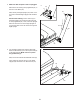
. Raise the Frame (56) to the upright position. IMPORTANT: Do not raise the Frame past the vertical position. Have a second person hold the Frame until step 16 is completed. 14 Orient the Latch Crossbar (114) as shown. Make sure that the “This side toward belt” sticker (J) is facing the treadmill. Attach the Latch Crossbar to the brackets (K) on the Frame (56) with two 5/16" x 3/4" Screws (6) and two 5/16" Star Washers (11). K 114 K 11 6 11 6 56 15.
16. Remove the 5/16" Nut (34) and the 5/16" x 2 1/4" Bolt (106) from the bracket on the Latch Crossbar (114). 16 34 M 114 Align the upper end of the Storage Latch (52) with the bracket on the Latch Crossbar (114), and insert the 5/16" x 2 1/4" Bolt (106) through the bracket and the Storage Latch. This will push a spacer (M) out of the Storage Latch; discard the spacer. 106 52 56 Next, tighten the 5/16" Nut (34) onto the 5/16" x 2 1/4" Bolt (106).
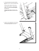
18. Attach the Tablet Holder (25) to the console assembly (F) with four #8 x 5/8" Machine Screws (8); start all four Screws, and then tighten them. Do not overtighten the Screws. 18 25 8 8 F 19. Make sure that all parts are properly tightened before you use the treadmill. If there are sheets of plastic on the treadmill decals, remove the plastic. To protect the floor or carpet, place a mat under the treadmill. To avoid damage to the console, keep the treadmill out of direct sunlight.
SP HOW TO USE THE TREADMILL HOW TO PLUG IN THE POWER CORD Follow the steps below to plug in the power cord. This product must be earthed. If it should malfunction or break down, earthing provides a path of least resistance for electric current to reduce the risk of electric shock. This product’s power cord has an equipment-earthing conductor and an earthing plug. IMPORTANT: If the power cord is damaged, it must be replaced with a manufacturer-recommended power cord. 1.
CONSOLE DIAGRAM FEATURES OF THE CONSOLE To turn on the power, see page 19. To use the manual mode, see page 19. To use an onboard workout, see page 21. To use an interval training workout, see page 22. To connect your smart device to the console, see page 22. To connect your heart rate monitor to the console, see page 23. To use the sound system, see page 23. To use the information mode, see page 24. To use the tablet holder, see page 24.
HOW TO TURN ON THE POWER HOW TO USE THE MANUAL MODE IMPORTANT: If the treadmill has been exposed to cold temperatures, allow it to warm to room temperature before you turn on the power. If you do not do this, you may damage the console displays or other electrical components. 1. Insert the key into the console. Plug in the power cord (see page 17). Next, locate the power switch on the treadmill frame near the power cord. Press the power switch into the reset position.
5. Change the incline of the treadmill as desired. 7. Measure your heart rate if desired. To change the incline of the treadmill, press the Incline increase and decrease buttons or one of the Quick incline buttons. Each time you press one of the buttons, the treadmill will gradually adjust to the selected incline setting. You can measure your heart rate using either the handgrip heart rate monitor or a compatible heart rate monitor.
8. When you are finished exercising, remove the key from the console. Each workout is divided into segments. One speed setting and one incline setting are programmed for each segment. Note: The same speed setting and/ or incline setting may be programmed for consecutive segments. Step onto the foot rails, press the Stop button repeatedly, and adjust the incline of the treadmill to zero. The incline must be at zero or you may damage the treadmill when you fold it to the storage position.
HOW TO USE AN INTERVAL TRAINING WORKOUT 6. Follow your progress with the displays. During an interval training workout, you will repeatedly alternate between intervals of low-intensity “recovery” exercise and intervals of high-intensity “work” exercise. See step 6 on page 20. The display will show the time remaining instad of the elapsed time. 7. Measure your heart rate if desired. 1. Insert the key into the console. See step 7 on page 20. See HOW TO TURN ON THE POWER on page 19. 8.
HOW TO CONNECT YOUR HEART RATE MONITOR TO THE CONSOLE When a connection is established, the LED on the console will flash blue. Press the Bluetooth button on the console to confirm the connection; the LED on the console will then turn solid blue. The console is compatible with all BLUETOOTH Smart heart rate monitors. 3. Record and track your workout information. To connect your BLUETOOTH Smart heart rate monitor to the console, press the Bluetooth button on the console.
THE INFORMATION MODE HOW TO USE THE TABLET HOLDER The console features an information mode that keeps track of treadmill usage information and allows you to select a unit of measurement for the console. You can use your tablet to browse media while you exercise. Place your tablet on the tablet holder and let the tablet holder hold your tablet in place. To select the information mode, insert the key into the console while holding down the Stop button. Then, release the Stop button.
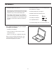
HOW TO FOLD AND MOVE THE TREADMILL HOW TO FOLD THE TREADMILL HOW TO MOVE THE TREADMILL To avoid damaging the treadmill, adjust the incline to zero before you fold the treadmill. Then, remove the key and unplug the power cord. CAUTION: You must be able to safely lift 45 lbs. (20 kg) to raise, lower, or move the treadmill. Before moving the treadmill, fold it as described at the left. CAUTION: Make sure that the latch knob is in the storage position. Moving the treadmill may require two people. 1.
MAINTENANCE AND TROUBLESHOOTING MAINTENANCE SYMPTOM: The power turns off during use Regular maintenance is important for optimal performance and to reduce wear. Inspect and properly tighten all parts each time the treadmill is used. a. Check the power switch (see drawing c at the left). If the switch has tripped, wait for five minutes and then press the switch back in. Regularly clean the treadmill and keep the walking belt clean and dry.
Locate the Reed Switch (107) and the Magnet (109) on the left side of the Pulley (49). Turn the Pulley until the Magnet is aligned with the Reed Switch. Make sure that the gap between the Magnet and the Reed Switch is about 1/8 in. (3 mm). If necessary, loosen the #8 x 1/2" Machine Screw (95), move the Reed Switch slightly, and then retighten the Machine Screw.
SYMPTOM: The walking belt is not centered between the foot rails. IMPORTANT: If the walking belt rubs against the foot rails, the walking belt may become damaged. SYMPTOM: The walking belt slips when walked on a. F irst, remove the key and UNPLUG THE POWER CORD. Using the hex key, turn both idler roller screws clockwise, 1/4 of a turn. When the walking belt is correctly tightened, you should be able to lift each edge of the walking belt 2 to 3 in. (5 to 7 cm) off the walking platform.
EXERCISE GUIDELINES Burning Fat—To burn fat effectively, you must exercise at a low intensity level for a sustained period of time. During the first few minutes of exercise, your body uses carbohydrate calories for energy. Only after the first few minutes of exercise does your body begin to use stored fat calories for energy. If your goal is to burn fat, adjust the intensity of your exercise until your heart rate is near the lowest number in your training zone.
PART LIST Key No. Qty. 1 2 3 4 5 6 7 8 9 10 11 12 13 14 15 16 17 18 19 20 21 22 23 24 25 26 27 28 29 30 31 32 33 34 35 36 37 38 39 40 41 42 43 44 45 46 47 48 49 50 23 4 2 29 4 2 4 4 4 1 6 4 8 14 3 1 2 1 4 2 2 2 4 2 1 4 1 4 1 4 1 2 6 6 4 1 6 2 4 2 1 1 1 1 1 2 1 4 1 2 Model No. PETL79816.0 R0416A Description Key No. Qty.
Key No. Qty. 101 102 103 104 105 106 107 108 1 4 2 1 8 1 1 1 Description Key No. Qty. Right Inner Base Cover 3/8" Plastic Bushing Roller Spacer Receptacle #8 x 3/8" Screw 5/16" x 2 1/4" Bolt Reed Switch Clip 109 110 111 112 113 114 115 * 1 2 1 2 2 1 1 – Description Magnet Motor Bushing Filter #8 Nut #8 x 1/2" Filter Screw Latch Crossbar Motor Isolator User’s Manual Note: Specifications are subject to change without notice.
15 14 59 30 34 23 66 39 97 32 40 14 61 37 43 14 14 57 44 15 11 35 66 39 97 6 37 14 14 40 23 42 14 45 46 35 47 59 30 34 37 19 30 60 34 56 35 37 34 59 21 37 52 66 95 35 53 109 14 97 39 49 107 106 11 6 103 108 23 51 55 95 114 66 34 15 54 46 37 59 30 34 103 112 14 97 19 39 98 23 110 20 115 41 48 21 53 51 95 95 73 111 99 95 24 113 113 EXPLODED DRAWING A Model No. PETL79816.
EXPLODED DRAWING B Model No. PETL79816.
EXPLODED DRAWING C Model No. PETL79816.
EXPLODED DRAWING D Model No. PETL79816.
ORDERING REPLACEMENT PARTS To order replacement parts, please see the front cover of this manual.