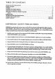
TABLE OF CONTENTS IMPORTANT SAFETY PRECAUTIONS ......................................... BEFOREYOU BEGIN ...................................................................... "................. 1 2 ASSEMBLY............................................................................. ADJUSTING THE CROSS TRAINERe .......................................................... 3 8 OPERATING THE STEPPERCONSOLE ......................................................... OPERAllNG THE PERSONAL TRAINER COMPUTER ...
BEFORE YOU BEGIN Congrafulatlons for purchasing the revolutionaryPROFORM" CROSS TRAINER e. The CROSS TRAINERe combines a multi-stationweight systemwith a full-size stepperto let you enjoy true cross training workoutsin the convenience of your own home. And fo help you get the mostfrom every workout, the CROSS TRAINERe features the advanced PERSONAL TRAINERTM weight training computer.
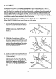
ASSEMBLY Assembly requires two persons.To assemblethe CROSS TRAINER e, usethe includedvideocassetteor follow the instructionsbelow. Due to the weight of the CROSS TRAINER e, it shouldbe assembledin the locationwhere it will be used. Place all parts in a cleared a_-,a and remove the packing materials. Do not disposeof the packing materials until assembly iscompleted.
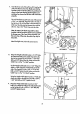
4. Slide the Brace(29) ontothethreadedboltprotruding fromthe TowerFrame(10). Threada 3/8" N/lock Nut (6) ontothe threaded bolt.Do notfighten the Nylock Nut yet. 4 29\6 Place your foot on the extension and sl_gh_raise the front ofthe Tower Frame (10). Align the lower " end of the Brace (29) with the indicated 3/8" x 2 1/2" Co,age Bolt (1). Lowerthe Tower Frame so the Brace slidesonto the Carriage Bolt. Thread a 3/8" Nut (2) with a 3/8" Lack'washer(3) onto the Carrloge Bolt. Do not tighten the Nut yet.
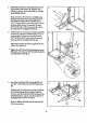
. Insert the lower enc[of the LeftArm (15) into the left side of the Moment Ann (74). Make sure that the bracket on the end of the LeftArm is positionedas shown in the insetdrawing. If the bracket is nat positioned as shown, the LeftAnn willnot function properly. Top a 3/4" PlasticCap (57) onto one of the ends of a 3/4" x 4" Axle (54). Align the hole in the end of the LeftArm (15} with the holes in the Moment (74). Insert the Axle into the Moment Arm and the LeftArm.
10. Wrap the Weight Cable (52) around a 2" Pulley (4). Attach the Pulleyto the RightArm (16) with a 3/8" x 1 3/4" Bolt(40) and 3/8" Nylock Nut (6). Lay theWeight Cable (52) over a 3 1/2' Pulley(5). Attach a Cable Trap (67) and the Pulley to the side of the Upright (9) with a 3/8" x 1 3/4' Bolt (40) and 3/8' Nylock Nut (6). Make sure that the Cable Trap is in the "12 o'clock" position. 11. Wrap the Weight Cable (52) under a 2" Pulley (4).
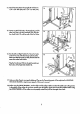
14. Attach the Seal (28} to the Upright (9) with the two 1/4" x 5/8" Baits (20} and a 1/4" x 2" Bolt(118). 14 15. Center one Pod Tube (22) in the Upright (9), and the other Pod Tube in the Leg Developer (23). Slide the four Small Pads (17) onto the ends of the Pad Tubes. 9 16. Restth.eLeftand Right Pedals (75, 76] on the honks • at the lower ends of the ResistanceCylinders (84). //17 16 Make sum that the hooks are f_ily inserted into the same slots under both Pedals.
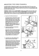
ADJUSTING THE CROSS TRAINER e The CROSS TRAINER • is deslgned to be changed from stationto station quickly and easily. The instru_ons below describe how each part of the CROSS TRAINER e can be adjusted. Please read these insf'nJdlonscarefully before using the CROSS TRAINER e. ReFerto pages 17 through 24 of this owner's manual to see how the CROSS TRAINER • should be set up for each individual exercise. IMPORTANT: For effecffve exercise, the CROSSTRAINERe must be set up correctly for each exercise.
4. ATTACHING THE I.AT BARI ROWER BAR OR STRAPTO THE LOW PULLEYSTATION Altach the tat Bar (36) la the Main Cable (51) with a Cable Cllp (33). For some exercises,the Chain (38) should be attached between the tat Bar and the 38 Main Cable with two Cable Clips. Adjust the length of the Chain between the/,at Bar and the Main Cable so the tat Bar is in the correct starffng posiffon for the exercise to be I:_'formed. 33 The Rower Bar (34} or the Strap (35) can be affached in the some manner.
OPERATING THE STEPPER CONSOLE The stepper console is designed to 91ve you instantfeedback as you exercise on the stepper. PTeoseread these instructionscarefvlly before operating the console. Note: Removethe clear plastic from the front of the console. DIAGRAM OF THE CONSOLE 1. LCD dispk_F-Display for all modes. 2. Mode incllcolors--Show which mode is currently selectedand displayed. 3. MODE button--Seleds modes. OISTANCE CALORIE MODE .4.
OPERATING THE PERSONAL TRAINER COMPUTER The heart of the CROSS TRAINER • is the advanced PERSONAl.TRAINER weight troining compufer.With the PERSONAL TRAINERcomputer, you can change the weight settingwile a touch of a button. As you exercise,lie compuferwill measureyour range oFmotion, show the number of Calories you have burned and keep frockof _ repetitionsand setsyou have complefod.
Next, press the TONE or STRENGTH button, depending on whether you wont the first exercise to be o tone or a strength exercise. The WEIGHT display will show the recommended weight setting for the exercise that you have selected. WARNING: The recommended weight settng may be too high or too low far you, depending upon such fadors as your body size and physical condition. If you cannot complete the desked numbers of sets and repetitions, the weight setting should be decreased.
Once you have selected the first musclegroup thatyou want to exercise, refer to the lower part af _e computer.One or mare indicatorswill be lightecl, showing you which exerclse(s)to do to develop the selectedmusclegroup. One of the indicatorswill be flashing to show you which exercise to do first. If you want to skip the first exercise,pressthe right arrow an the NEXT button until the indicator is flashingon the exercise that you want to do first.The number of the exercise will be shown in the CAi.
After you have applied a decal to the exercise insertfor each of the exercisesthat you want to include in your first workout, fit the four tabs on the insert into the slots in the lower part of the computer. Make sure that the insert is turned so the decals are visible. (The use of the remaining spaceson the insert will be explained below.) Next, a weight, set and repetition settingshould be programmed for each of the exercises, and the workout shouldbe stored on the CUSTOM SMART CARD.
TURNING OFF THE POWER To turn off lee power, press lee I_WER button.Note: If no butlons on _ computer am'pressed for 30 m_nutes,the power will turn off automatically. The transformershouldbe unplugged from lee 120"volt outle! during periodsof rlONUSO.
EXERCISE GUIDE SAFETY The CROSS TRAINER • is a tool, and leamlng lo use it properly is essentialfor your safety as well as the success oF your exercise program. Read this owner's manual and the accompanying FITNESSJOURNAL carefully before usingthe CROSS TRAINER e. Remember, the information in this owner's manual and in the FITNESSJOURNAL is general in nature. For more information about exercise, consultyour physklan or obtain a reputable book about exercise.
1. BUTTERFLY (15-125 Lbs.) J_usclesaF[ectacJ: pedoral_s maior and m[nor, dellolcls Re_ to adjustment 2 on Page 8 of thisownePs manual. Change the arms to the but" tartly mode. Sit on t_ seat and hold the pods on the arms as shown;your arms shouldbe bent at 90 ° angles. Keep your hock straight. Pressthe arms together until the pods touch. Relum to the starting position. 2. BENCH PRESS (30-250 Lbs.
6. LATERALARM RAISE (15-125 Lbs.) Musclesaffecfed:deltoids, tropezlus ReFerto adjustment4 on page 9 of this owner's manual. Attach the shop to the low pulley statlon. Sfand with your side toward the CROSS TRAINER • with your feet on the foot plate. Hold the stropwith an overhand grip with your arm at your side. Keep your back straight. Raise the stropto the side until your hand is level with your shoulder as shown. Returnto the starting position. 7.
11. LEG EXTENSION (15-125 Lbs.) MusclesaF[eded: quadrlceps Sit on the seat end position your feet under the pads on the leg developer. Keep your back straight. Roisethe leg developer unfityour legs ore straight. ReturnIo the starting position. 12. HIP ABDUCTION (15-125 Lbs.) Muscles affec_d:abc/ucl_r,gluteusmedlus Refer to adjustment 4 on page 9 of th;s owner's manual. Attach the strap to the low pultey station. Stand with your side toward the CROSS TRAINER e with one foot on the foot plate.
16. SINGLE LEG CURL (15-125 Lbs.) Musclesaffected:hamstring,gastrocnemlus StandfacingtheCROSSTRAINER• and restthe backof one legagainstthe lower pod onthelegdeveloper. Raisethelegdeveloperas far as passibleby bendingyour legasshown.Returnto the startingposition. 17. AB CRUNCH (15-125 Lbs.) Muscles affected: reclusal_Jominus, upper abdornlnals Referta adjustment 3 on Page 8 of thisowner'smanual.Attach theslrap to the high pulleystation.Siton the seatand hold the strapbehindyourheadas shown.
A. SIDE BEND (15-125 Lbs.) Musclesaffected:laEsslmusdorsl, biceps, posterior deltoids Referto adjustment4 on page 9 of this owner's manual. Attach the strap to the low pulley station.Standwith your side toward the CROSS TRAINER e with one foot on the foot plate. Hold the strapwith an overhand grip with your arm at your side. Keep your back straight.Bendtoward the side as shown. Returnto the starting position. B. LATPULL-DOWN--CLOSE GRIP (15-125 Lbs.
F. SINGLE ARM BENT ROW (15--125 Lbs.) MusclesaA_c'led:biceps,brachiaredials, deltoids,Irapezius, lah'ssimusdorsi, rhombo;ds Refer to adjustment 4 on page 9 of this owner's manual. A_ach the strap to the low pulley station. Stand with your feet on the foot plate and bend forward as shown. Hold the strap with an overhand grip with your arm extended downward. Keep your back straight. Pullthe strap toward your stomach. Returnto the starting position. G. SEATED ROW--WIDE GRIP (15-125 Lbs.
K. BENT ISOLATION CURL (15--125 Lbs.) MusclesatTectecl: biceps,brachloradlals Refer ta adjustment4 on Page 9 of this owner's manuQI. ,6,ffoch_ stropto the low pulley station. Stand with your side _.ward the CROSS TRAINER e, place one foot on the foot plate and bend forward as shown. Hold the stropwith on underhand grip with your elbow restingagainst your kneeand your arm extended downward. Pull the strap up until your hand is level with your chest. Returnto the storffng position. L.
P. BENT LATERAL ARM RAISE(15-125 Lbs.) Musclesaffected:deltoids,trapezius Refer ta adjustment4 on page 9 of this owner's manual. Attach the strap to the low pulley station. Stand with your side toward the CROSS TRAINER e, place one foot on the foot plate and bend forward as shown. Hold the strap with an overhand grip with your arm at your side. Keep your back straight. Raise the strap to the side until your hand is level with your shoulder. Return to the starting position. Q. DEAD LIFT (15-125 Lbs.
TROUBLE-SHOOTING AND MAINTENANCE Inspectand tighlenall parts each time you usethe CROSS TRAINERe. Replace any warn parts immediately. Outside surfacesof the CROSS TRAINERe can be cleaned using a damp clothand mild detergent. Keep all liquids away from the stepperconsole and the PERSONALTRAINER computer. Most CROSSTRAINER• problems can be solvedby following the slaps below. Find the applicable symptom and fallow the slap(s)lided.
b. If the LCD display becomes dim, the 1.5-volt watch batteries in the Stepper Console (88) should be replaced. Using a shortphillips screwdriver, remove the two screws attaching the back of the Stepper Console. Using the screwdriver,carefully push the two ba_ries out of the barry d;ps; be careful to note which way the batteries ore turned. Insert two new 1.5-yah watch batteries into the 1.5-Volt Watch Batteries battery clips. Reat/achthe back of the Stepper Console. 4.
EXPLODED DRAWING--MODEL NO. 831.
• E..X..pl nn,-,-, DRAWiNG-MODEL w- NO. 831.159341 R694A I0 16 97 6/ 1: 77 94 119 o 98 19".
SEARS MODEL NO: 831.
SEARS MODEL NO: 831.
SEARS MODEL NO: 831.
SEARS MODEL NO: 831.159341 PRODUCT NAME: PROFORM CROSS PRODUCT DESC: TRAINER RUN RUN KEY DESCRIPTION COST NUMBER PART NUMBER DATE: TIME: .........................
SEARS MODEL NO: 831.159341 PRODUCT NAME: PROFORM CROSS PRODUCT DESC: TRAINER RUN RUN KEY DESCRIPTION COST NUMBER PART NUMBER DATE: TIME: ..................................................
ORDERING REPLACEMENT PARTS Each CROSS TRAINER e has itsown MODEL NUMBER. Ab_::ys mention this MODEL NUMBER when requesting service or repair paris for your CROSS TRAINER e. All parts llsted herein can be ordered through SEARS, ROEBUCKAND CO. SERVICECENTERSand most SEARS RETAILSTORES.If parts you need are not stockedlocally,your order will be transmitted to a SEARS PARTSDISTRIBUTION CENTERfor handling. WHEN ORDERING REPAIRPARTS,ALWAYS GIVE THE FOLLOWING INFORMA11ON: 1. The MODEL NUMBER af the product (831.