TABLE OF CONTENTS IMPORTANT SAFETY PRECAUTIONS .......................................................... BEFOREYOU BEGIN ...................................................................... ./ 2 ASSEMBLY ............................................................................. ADJUSTING THE CROSS TRAINER e ........................................................... TROUBLE-SHOOTING AND MAINTENANCE .................................................... 3 8 9 OPERATING THE STEPPERCONSOLE ..........
RE YOU BEGIN ,hans for purchasing the revabtioeary PROFORM* CROSS TP,_NER e. The CROSS TP-_NER e comb;nes ¢ .arian weight system with a full-slze stepper to let you enjoy true cross tra_ning workou_ in the convenience oF • -,ur own home. And to help you get the mast from every workout, the CROSS TRAINER e fea_res the advanced PERSONAL TP,AINER TM weight training computer.
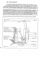
ASSEMBLY Assembly requires two persons. To assemble the CROSS TRAINER e, use the included videocassette or follow the instructions below. Due to the weight oFthe CROSS TRAINER e, it should be assembled in the location where it will be used. Place all ports in o cleared area and remove the packing materials. Do not dispose of the packing materials until assembly is completed.
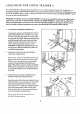
. ._ilc_ethe Brace (29) onto the threaded boff protruding from the Tower Frame (10). Thread a 3/8" 4 Nylock Nut (6) onto the threaded bolt. Do not tighten the Nytock Nut yet. 29 6\ Place your Foot on lhe extension and slighl_yraise the front of the Tower Frame (10). Align the lower • end oFthe Brace (29) with the indicated 3/8" x 2 1/2" Carriage Bolt (1). Lower the Tower Frame so the Brace slidesonto the Corrlage Bolt. Thread a 3/8" Nut (2) with a 3/8" Lack'washer(3) onto the Carriage Bolt.
. Insert the lower end oF _ne Le[t Arm (15) into the refi' 7 side of the Moment Arm (74). Make sure that the bracket on the end of the Left Arm is positioned as shown in the inset drawing. If the bracket is not positioned as shown, the Left Arm will not function properly. Align the hole in the end of the Le[t Arm (15) with the holes in the Moment Arm (74_. Insert the 3/4" x 4" Axle (54) into the Moment Arm and the Left Arm. Tap a 3/4" Plastic Cap (57) onto the Axle.
10. Wrap the Weight Cable (52) around a 2" Pulley (4). 10 Attach the Pu]Yeyto the Right Arm (16) with a 3/8" x 1 3/4" BOlt(40) and 3/8" 4O N/lock Nut (6). Lay the Weight Cable (52) over a 3 1/2" Pulley (5). Attach a Cable Trap (67) and the Pulley to the side of the Upright (9) with a 3/8" x 1 3/4" Bolt (40) and 3/8" N/lock Nut (6}. ' _ake sure that the Cobb Trap is in the "12 o'clock" position. 1 I. Wrap the Weight Cable (52) under a 2 3/4' Pulley (13).
14. Attach the Seat (28) to the Upright (9} with the two 1/4" x 3/4" Bolts (20) and a 1/4" x 2 1/2" Bolt (46). 15. Center one Pad Tube (22) in the Upright (9), and the other Pad Tube in the Leg Developer (23). Slide the four Small Pods (17) onto the ends of the Pad Tubes. 16. Rest the Left and Right Pedals (75, 76) on the hooks at the lower ends of the Resistance Cylinders (84). Make sure that the hooks are fully inserted into the same slots under both Pedals.
ADJUSTING THE CROSS TRAINER e The CROSS TRAINER e is designed to be changed from stc'bn to station quickly and easily. The instruc'ffons b_Jow describe how each part of the CROSS TRAINER e can be adiusted. Please read these instructions carefully before using the CROSS TRAINER e. ReFerto pages 17 through 24 o_ this owner's manual to see how the CROSS I"R,_NER e should be set up for each individual exercise.
_° AI"T._,CHING THE I-AT BAR, ROWER BAR OR STRAP TO THE LOW PULLEY STATION Attach the Lot Bar {36} to the Main Cab}e (51) with a Cable Clip (33). For some exercises, the Chain (38} should be attached betweenthe LOtBar and the 38 34 Maln Cable wlth two Cable Clips. Adjust the length of the Chain between the Lot Bar and the Main Cable so the Lot Bar is in the correct starting position for the exercise to be performed. 33 The Rawer Bar (34} or the Strop (35) can be altached in the same manner.
3. SYMPTOM: THE STEPPERCONSOLE DOES NOT FUNCTION PROPERLY O. As you step, move the stepper pedals vertically at least 8 inches. IFyour stepsore too shallow, the movement oF the stepper pedals will not be detected. IFthe stepper console still does not 92 function properly, loosen the Reed Switch Screw 99 \ (92). Hold down the Right Pedal (76). Adjust the position of the Reed Switch (99) so there is a 76 ff----T 1/8" gap between the Reed Switch and the \ Magnet (81) on the Right Pedal.
OPERATING THE STEPPER CONSOLE The stepper console is designed to give you instant _:eedbackas you exercise on the stepper. Please read these instructions carefully before operating the console. Note: Remove the clear plastic kom the front of the conso]e. DIAGRAM OF THE CONSOLE 1. LCD display -Display for all modes. 7;ME 2. Mode indicators--Show which mode _scurrently seleded and d_spbyed. 3. MODE button--Selects modes. 4.
OPERATING THE PERSONAL TR AINER COMPUTER The heart oFthe CROSS TRAINER e is the advanced PERSONAL TP_NER computer. With the PERSONAL TRAJNER computer, you can change the weight settingwith a touch of a button. As you exercise, the computer will measure your range of motion, show the number of Calorles you have burned and keep track of the repetitions and setsyou have completed.
The WEIGHT display will show the recommended weight serffngfor the exercise that you have selected. WARNING: • The recommended weight setting may be too high or too low for you, depending upon such factors as your body s_ze and physical condition. If you cannot com.olete the desired numbers of sets and repetitions, the weight setting should be decreased. The weight setting con be changed by pressing the increase or decrease button beneath the WEIGHT display.
yOU have selected the first muscle grou p that you want to exercise, refer to the lower pad of the computer. One or more :,ndicators will be lighted, showing you which exerc_sels) to do to develop the selected muscle group. One of the indicators will be Flashing to show you which exercise to do first. If you want to skip the first exercise, press the rlc L' arrow on the NEXT button until the indicator is flashing on the exc rc_sethat you want to do first.
After you have applled-a decal to the exercise insert for each oF the exercises that you want to include in your first workout, fit the four tabs on the insert into the slo_ in the lower part oFthe computer. Make sure that the insert is turned so the spaces on the insert numbered 1 !'..'ough 20 are vlsible (The use oFthe remaining spaces on the insert will be explained later.
EXERCISE GUIDE SAFETY The CROSS TRAINER e is a tool, and leamlng ta use it properly is essential for your safety'as well as the successof your exercise program. Read this ownerls manual and the accompanying FITNESSJOURNAL carefully before using the CROSS TP,AINER e. Remember, the information in this owner's manual and in the FITNESSJOURNAL is general in nature. For more informofio., about exercise, consult your physician or obtain a reputable book about exercise.
1. BUTTERFLY (15-125 Lbs.) Muscles affected: pectoralls ma_or and minor, deltoids ReFerto adjustment 2 on page 8 of thisowner's manual. Change the arms to the butlerfly mode. Sit on the seat and hold the pads on the arms as shown; your arms should be bent at 90* angles. Keep your back straight. Press the arms together until the pads touch. Returnto the starting position. 2. BENCH PRESS (30-250 Lbs.
6. LATERALARM RAISE (15.125 Lbs.) Muscles affec'_: deltoids,h'apezbs Refer to adjustment4 on page 9 of this owner's manual. Attach the strap to the low pulley station. Stand with your side toward the CROSS TRA)NER e with your Feeton . the Footplata. Hold the strop with an overhand grip with your arm at your side. Keep :_ your back straight. Raise the strap to the s[de until your hand is level with your shoulder as shown. Returnto the starting position. 7. SEATED ROW--CLOSE GRIP (15-125 Lbs.
11. LEG EXTENSION (15-125 Lbs.) Muscles affected: quadriceps Sit on the seat and position your feet under the pods on the leg developer. Keep your back straight. Raise the leg developer unlflyour legs are straight. Return to the start_ngposition. 12. HIP ABDUCTION (15-125 Lbs.) Musclesaffected:abductor,gluteusmedius Refer to adjuslment4 on page 9 of _is owner's manual. Attach the strap to the low pulley station. Stand with your side toward the CROSS TRAINER e with one foot on the foot plate.
16. SINGLE LEG CURL (15-125 Lbs.) Muscles affected: hamstring, gastrocnem;us Stand facing the CROSS TRAINER e and rest the back oFone leg against the lower _ pad on the leg developer. Ralse the leg developer as far as possible by bending your leg as shown. Rel_rn to the starting position. 17. AB CRUNCH (15-125 Lbs.) Musclesaffected:reclus abdominus, upper abdomlnals Refer to adjustment 3 on page 8 of this owner's manual. Attach the strap _ the hlgh pulley station.
A. SIDE BEND (15-125 Lbs.) Musclesoff_ed: le_'ssimusdcrsi, biceps,posterior deltoids • Referto adjustrne_nt 4 on page'9 of thisowner'smanual.Attach the strapto the low pulleystation.Standwith your sldetoward the CROSSTRAINERe withone footon _ the footplate.Hold thestrapwith an overhandgrip with yourarm at your•side. Keep your back straight.Bendtoward the sideas shown.Returnto the s_artingposition. B. LAT PULL-DOWN--CLOSE GRIP (15-125 Lbs.
F. SINGLEARM BENT ROW (15--125 Lbs.) Muscles affected: biceps, brachioradlals, deltoids, tropezlus, laHsslmusdorsi, rhom,,oids Refer to adjustment 4 on page 9 of this owner's manual. Attach the strap to the Iowlz pulley stoHon.Stand with your feet on the foot plate and bend forward c_ shown. :'_ : Hold the strap with an overhand grip with your arm extended downward. Keep your back straight. Pull the strap toward your stomach. Return to the starting Pasltbn. G. SEATED ROW-WIDE GRIP (15--125 Lbs.
K. _ BENT ISOLATION Mu. .:es a_-'ted: " - CURL (15--125 Lbs.) biceps, _rachbradlals Refer to adjustment 4 on page 9 of this owneds manual. Attach the strap to the low : pulley s_tion. Stand with your side toward the CROSS TRAINER e, place one foot on the foot plate and bend forward as shown. Hold the strap with an underhand grip i with your elbow resting against your knee and your arm extended downward. Pull : the strap up until your hand is level with your chest, Return to the starting Posit_on. L.
P. BENT LATERAL ARM RAISE (I 5-I 25 Lbs.) Muscles affected: delto;ds,trapezlus Refer to adjustment 4 on page 9 oF this owner's manual. Attach the strap to the low pulley station. Stand withyour side toward the CROSS TRAINER e, place one foot on the foot plate and bend forward as shown. Hold the strap with an overhand grip_ with your arm at your side. Keep your back straight. Raise the strop to the side until your hand is level with your shoulder.Return to the starting position. Q. DEAD LIFT(15.125 Lbs.
ORDERING REPLACEMENT PARTS EachCROSSTRAINERe has itsownMODELNUMBER.Always mentionthisMODEL NUMBERwhen requestingservice or repairpa_ for your CROSSTRAINERe. All Po_ listedherein can be orderedthrough SEARS,ROEBUCKAND CO. SERVICECENTERSand mostSEARS RETAILSTORES.If paris you needore not slackedlocally, your orderwill be transmil_edto a SEARSPARTSDISTRIBUTION CENTERfor handling. WHEN ORDERINGREPAIRPARTS,ALWAYS GIVETHEFOLLOWINGINFORMATION: 1. TheMODELNUMBERof the product (831.159341). 2.