Model No. 831_|57033 Serial No. TM Serial Number Decal MULTI-DIMENSIONAL TRAINING 250 RESISTANCE LBS ELECTRONIC SEA// 6 CA UTION: SOLD BY SEARS, precautions Save this manual ROEBUCK CONTROL OWNER'S MANUAL Read all safety using this equipment. SYSTEM and Instructions for future AND CO., CHICAGO, in this manual carefully before reference.
TABLE OF CONTENTS Important Safety Precautions ....................... Before You Begin ................................ Assembly ....................................... Operation and Adjustment ......................... Maintenance and Trouble-Shooting .................. Exercise Guidelines .............................. Part List ........................................ Exploded Ordering Warranty Drawing ................................ Replacement Parts ................ ................................
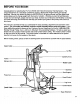
BEFORE YOU BEGIN Congratulations for selecting the Pro Form EDGE 4001 Multi-Dimensional Training System. The unique EDGE 4001 is a total body conditioning system, offering both weight training and aerobic exercises. Moving from station to station on the EDGE 4001 is quick and easy, and the digital hand control allows you to change weight with the touch of a button.
ASSEMBLY Two persons are recommended in order to assemble the system. Set all parts in a cleared area. Make sure that all parts are Included before disposing of the packing materials. Read each step carefully before beginning. Assembly can be completed using a standard screwdriver and two adjustable wrenches (not included). ° Press a Front Stabilizer Endcap (70) onto each side of the front stabilizer of the Frame (1). Slide the Base Extension (47) onto the Frame, and align the holes.
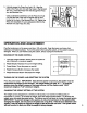
, Liberally grease the Press Arm Axle (10). Align the holes in the Press Arm (12) with the holes in the Moment Arm (13). Insert the Press Arm Axle through the Press Arm and Moment Arm. 5 I --1 grease Using a standard screwdriver, turn the Press Arm Axle (10) until the hole in the Axle is aligned withthe hole located at the front of the Moment Arm (13). "13ghtenthe Press Arm Axle Bolt (11) and Lockwasher (66) into the Moment Arm and Press Arm Axle.
ATTACHINGAND REMOVINGTHESEAT SUPPORT The seat support should be attached to the system;/as described in the assembly instructions. For certain exercises, the seat support must be removed. First, remove the lower cable from the leg lever. Then, lift the seat support until the bracket on the seat support is free of the pins on the frame.
ATTACHING THE ABDOMINAL SYSTEM STRAP TO THE WEIGHT The abdominal strap is designed to be used with the middle cable. Remove any attachments from the middle cable. Attach the abdominal strap to the middle cable with a connector link. ATTACHING THE ANKLE STRAP The ankle strap is designed to be used with the lower pulley. Remove any attachments from the lower pulley. The cable extension can be attached between the ankle strap and the lower cable with two connector links.
LUBRICATING THE BUTTERFLY ARMS AND PRESS ARM The butterfly arms and press arm should be lubricated every six months with a petroleum-base grease. To lubricate the butterfly arms; remove the hairpin cotter pins and slide the butterfly arms off of the frame. Grease the bushings in the butterfly arms. Reattach the butterfly arms with the hairpin cotter pins. To lubricate the press arm, an adjustable wrench is required. Remove the bolt and Iockwasher from the lower end of the moment arm.
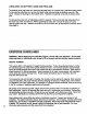
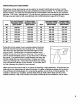
CARDIOVASCULAR CONDITIONING The leg lever, lat bar and press bar can be used for an excellent cardiovascular workout. Set the weight at the lowest setting and do as many repetitions and sets as desired. For an effective cardiovascular workout, your heart rate should be kept at a level between 70% and 85% of your maximum heart rate. This is your "training zone." You can find your training zone by consulting the table below.
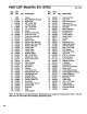
PART LIST- Model No. 831.157033 Key No. Part No. Qty. 1 2 3 NSP 105317 012108 1 2 17 4 5 6 7 104049 108190 013580 013341 8 9 10 11 12 13 : Description Rev. 3/92 Key No. Part No. Qty. Frame Rear Stabilizer Endcap NylockNut 41 42 43 103805 107379 104794 4 1 1 Leg Lever Pad Leg Lever Leg Lever Endcap 2 4 8 3 3/8"x3.50" Bolt L-Pulley Guard 3/8" x 2.00" Bolt 1/4" x 2.
EXPLODED DRAWING- Model No. 831,157033 Rev.
ORDERING REPLACEMENT PARTS Each EDGE 4001 System has its own MODEL NUMBER. Always mention the MODEL NUMBER when requesting service or repair pads for your EDGE 4001. All parts listed herein may be ordered through SEARS, ROEBUCK AND CO. SERVICE CENTERS and most SEARS RETAIL STORES. If parts you need are not stocked locally, your order will be electronically transmitted to a SEARS PARTS DISTRIBUTION CENTER for expedited handling. WHEN ORDERING REPAIR PARTS, ALWAYS GIVE THE FOLLOWING INFORMATION: 1.