Model No. 831.150330 Serial No. Write the serial number in the space above for reference. WEIGHT BENCH EXERCISER User's Manual Serial Number Decal (under seat) • Assembly • Adjustments • Part List and Drawing Patent Pending _I_CAUTION Read all precautions and instructions In this manual before using this equipment. Save this manual for future reference.
TABLE OF CONTENTS WARNING DECAL PLACEMENT .......................................................... IMPORTANT PRECAUTIONS ............................................................. BEFORE YOU BEGIN ................................................................... ASSEMBLY ........................................................................... ADJUSTMENTS ...................................................................... EXERCISE GUIDELINES ......................................................
IMPORTANT PRECAUTIONS WARNING: To reduce the risk of serious injury, read the following important precautions before using the weight bench. 1. Read all instructions in this manual before using the weight bench. Use the weight bench only as described in this manual. 11. Make sure that the set screws attaching the Olympic weight adapters are properly tightened each time the adapters are used. 2.
BEFORE YOU BEGIN Thank you for selecting the versatile PROFORM ® C800 weight bench. The weight bench offers an impressive array of weight stations designed to develop every major muscle group of the body. Whether your goal is to tone your body, build dramatic muscle size and strength, or improve your cardiovascular system, the weight bench will help you to achieve the specific results you want. reading this manual, call 1-80O-4-MY-HOME® (1-800-469-4663).
ASSEMBLY • Place all parts in a cleared area and remove the packing materials. Do not dispose of the packing materials until assembly is completed. Make Things Easier for Yourself This manual is designed to ensure that the weight bench can be assembled successfully by anyone.
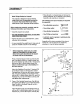
3. Attach the Leg Lever Bracket (7) to the Bench Frame (1) with two M10 x 81mm Button Bolts (75) and two M10 Nylon Locknuts (69). 3 7 Lubricate Press two 50mm Square Inner Caps (17) into the Leg Lever (4). Press a 25mm Round Inner Cap (20) into the indicatedend of the Weight Tube (11). 4 Attach the Weight Tube (11) to the Leg Lever (4) with an M8 x 63mm Button Bolt (71), two M8 Washers (73), a 13ram Spacer (25), and an M8 Nylon Locknut (72).
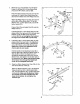
Insert the Backrest Bracket (10) through the slot in the Bench Frame (1) and under the Adjustment Lever (8). Make sure that the M10 x 65mm Flat Head Screw (77) is under the Backrest Bracket arm. 6 69 67 Lubricate an M1O x 155mm Button Bolt (85) with grease. Attach the Backrest Tubes (6) to the Bench Frame (1) with the Bolt, two M10 Washers (67), and an M10 Nylon Locknut (69). Do not overtighten the Locknut; the Backrest Tubes must be able to pivot easily.
9. Slide a Pad Tube (50) into a hole in the Leg Lever (4). Wet both sides of the Pad Tube with soapy water. Slide two Large Foam Pads (51) onto the Pad Tube as shown. Press two Large Pad Caps (53) into the Pad Tube. Repeat with the other Pad Tube and the Leg Lever. 54 53 52 4 50 / Slide the Long Pad Tube (82) into the hole in the Leg Lever Bracket (7). Wet both sides of the Pad Tube with soapy water. Slide two Small Foam Pads (52) onto the Tube as shown. Press two Small Pad Caps (54) into the Pad Tube.
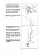
12. Attach a Base Cap (9) and a Rear Support (29) to the a Base (28) with two M10 x 93mm Button Bolts (48), an M10 Washer (67), an M10 Nylon Locknut (69), an MI0 Nylon Jamnut (26), and an M4 x 16mm Screw (58). 12 Repeat this step with the other Base (28) and Rear Support (29). 69 13. Attach a Base (28) to the Center Base (27) with three M10 x 68mm Button Bolts (79), three M10 Washers (67), and two M10 Nylon Locknuts (69). Do not tighten the Locknuts yet.
15. Using a rubber mallet, tap the left Rack Foot (35) into the indicated Base (28). Attach the Foot to the Base with two M1O x 65mm Button Bolts (60), four M10 Washers (67), and two M10 Nylon Locknuts (69). Do not tighten the Locknuts yet. 15 31 Attach the Left Upright (31) to the Rear Support (29) with two M10 x 68mm Button Bolts (79) and two M10 Nylon Locknuts (69). Do not tighten the Locknuts yet. 79 Attach the right Rack Foot (not shown) and Right Upright (not shown) in the same manner. 79 " 16.
18. Press a Top Bracket Bushing (55) into the Top Bracket (36). Using a rubber mallet, tap the Top Bracket onto the Left Upright (31) and the Guide Bar (32). 18 56i 67--*_._ 36 Attach the Top Bracket (36) to the Left Updght (31) with two M10 x 65mm Button Bolts (60), four M10 Washers (67), and two M10 Nylon Locknuts (69). Do not tighten the Locknuts yet. 67 " Attach the Top Bracket (36) to the Guide Bar (32) with an Mt0 x 30ram Button Screw (56) and an M10 Washer (67).
ADJUSTMENTS This section explains how to adjust the weight bench. See the EXERCISE GUIDELINES on page 15 for important informationabout how to get the most benefit from your exercise program.Also, refer to the accompanying exercise guide to see the correct form for each exercise. Make sure all parts are properly tightened each time the weight bench is used. Replace any worn parts immediately. The weight benchcan be cleaned with a damp clothand a mild, non-abrasivedetergent.Do not use solvents.
USING THE BENCH FOR PRESS EXERCISES To prevent the weight rack from tipping while performing press exercises on the bench, set the "L"-bracket (76) over the Center Base (27). 27 J USING THE OLYMPIC WEIGHT ADAPTER Press a 48mm Round Inner Cap (16) into the Olympic Adapter (15). Attach the Olympic Adapter to the Weight Tube (11) with a 1/4" x 9.5ram Allen Head Set Screw (66). Make sure that the Set Screw is in the bottom of the Adapter. 11 15 Press a 48ram Round Inner Cap (16) into a Weight Adapter (49).
ATTACHING WEIGHTS TO THE BARBELL OR THE WEIGHT CARRIAGE 84 41 To use the barbell, slide the desired amount of weight (not included) onto the Barbell Adapters (41). Secure the weights with the Large Weight Clips (84). WARNING: Donotplace more than 310 pounds on the barbell. Always place the same amount of weight on each side of the barbell, Always secure weights with the Large Weight Clips (84).
EXERCISE GUIDELINES THE FOUR BASIC TYPES OF WORKOUTS PERSONALIZING YOUR EXERCISE PROGRAM MUSCLE BUILDING To increase the size and strength of your muscles, push them close to their maximum capacity. Your muscles will continuallyadapt and grow as you progres÷ sively increase the intensityof your exercise. You can adjust the intensity level of an individualexercise in two ways: • by changing the amount of resistance used • by changing the number of repetitions or sets performed.
Rest for a short period of time after each set. The ideal resting periods are: • Rest for three minutes after each set for a muscle building workout. • Rest for one minute after each set for a toning workout. • Rest for 30 seconds after each set for a weight loss workout. Plan to spend the first couple of weeks familiarizing yourself with the equipment and learning the proper form for each exercise. COOLING DOWN End each workout with 5 to 10 minutes of stretching.
MONDAY EXERCISE WEIGHT SETS REPS WEIGHT SETS REPS WEIGHT SETS REPS Date: / / AEROBIC EXERCISE TUESDAY Date: ! / WEDNESDAY EXERCISE Date: / / THURSDAY AEROBIC EXERCISE Date: / / FRIDAY EXERCISE Date: / / Make photocopies of this page for scheduling and recording your workouts.
MONDAY EXERCISE WEIGHT SETS REPS WEIGHT SETS REPS WEIGHT SETS REPS Date: / / TUESDAY AEROBIC EXERCISE Date: / / WEDNESDAY EXERCISE Date: / / THURSDAY AEROBIC EXERCISE Date: / / FRIDAY EXERCISE Date: / / Make photocopies of this page for schedulingand recording your workouts.
MONDAY EXERCISE WEIGHT SETS REPS WEIGHT SETS REPS WEIGHT SETS REPS )ate: / / TUESDAY AEROBIC EXERCISE Date: / / WEDNESDAY EXERCISE Date: / / AEROBIC EXERCISE THURSDAY Date: / / EXERCISE FRIDAY Date: ! I Make photocopies of this page for scheduling and recording your workouts.
PART LISTmModel Key No. Qty. 1 2 3 4 5 6 7 8 9 10 11 12 13 14 15 16 17 18 19 20 21 22 23 24 25 26 27 28 29 30 31 32 33 34 35 36 37 38 39 40 41 42 43 44 45 46 1 1 1 1 1 2 ! 1 4 1 1 1 1 1 1 3 2 1 4 5 1 1 2 1 1 2 1 2 2 1 1 2 1 1 2 2 1 2 1 1 2 2 8 4 2 2 No. 831.
PART IDENTIFICATION CHART This chart is provided to help you identify the small parts used in assembly. The number in parenthesis below each part refers to the key number of the part from the PART LIST in the center of this manual. Important: Some parts may have been pre-assembled for shipping purposes. If a part is not in the parts bag, check to see if it has been pre-attached. If a part is missing, call toll-free 1-800-999-3756.
56 14 74 43_, 67 33 68 69 74 42 41 32 46 79 29 23 1 67 20 .÷....÷ .o--°_ 71 35 53 54 67_ 16 58 _56 52 i 58 ':;o Co Q t..
Get it fixed, at your home or ours! Your Home For repair - in your home - of all major brand appliances, lawn and garden equipment, or heating and cooling systems, no matter who made it, no matter who sold it! For the replacement par_s, accessones, and user's manuals that you need to do-it-yourself. For Sears professional installation of home appliances and items like garage aoor openers and water heaters. 1-800-4-MY-HOME_ tl-800-469-4663) www.sears.com Anytime,dayor night (U.S.A.and Canada) www.sears.