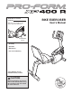
Model No. 831.21752.0 Serial No. Write the serial number in the space above for reference. Serial Number Decal • Assembly • Operation • Maintenance • Part List and Drawing Sears, Roebuck and Co. Hoffman Estates, IL 60179 CAUTION Read all precautions and instructions in this manual before using this equipment. Keep this manual for future reference.
TABLE OF CONTENTS WARNING DECAL PLACEMENT . . . . . . . . . . . . . . . . . . . . . . . . . . . . . . . . . . . . . . . . . . . . . . . . . . . . . . . . . . . . . .2 IMPORTANT PRECAUTIONS . . . . . . . . . . . . . . . . . . . . . . . . . . . . . . . . . . . . . . . . . . . . . . . . . . . . . . . . . . . . . . . .3 BEFORE YOU BEGIN . . . . . . . . . . . . . . . . . . . . . . . . . . . . . . . . . . . . . . . . . . . . . . . . . . . . . . . . . . . . . . . . . . . . . .4 ASSEMBLY . . . . . . . . . . . . .
IMPORTANT PRECAUTIONS WARNING: To reduce the risk of serious injury, read all important precautions and instructions in this manual and all warnings on your exercise bike before using your exercise bike. Sears assumes no responsibility for personal injury or property damage sustained by or through the use of this product. 9. Wear appropriate clothes while exercising; do not wear loose clothes that could become caught on the exercise bike. Always wear athletic shoes for foot protection. 1.
BEFORE YOU BEGIN Thank you for selecting the PROFORM® XP 400 R exercise bike. Cycling is an effective exercise for increasing cardiovascular fitness, building endurance, and toning the body. The XP 400 R exercise bike provides an impressive selection of features designed to make your workouts at home more effective and enjoyable. after reading this manual, please see the back cover of this manual. To help us assist you, note the product model number and serial number before contacting us.
ASSEMBLY Assembly requires two persons. Place all parts of the exercise bike in a cleared area and remove the packing materials. Do not dispose of the packing materials until assembly is completed. In addition to the included tool(s), assembly requires an adjustable wrench . screwdriver and a Phillips See the drawings below to identify the small parts needed for assembly. The number in parentheses below each drawing is the key number of the part, from the PART LIST near the end of this manual.
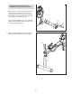
1. 1 To make assembly easier, read the information on page 5 before you begin. With the help of another person, lift the Frame (1) and place a packing insert (not shown) under the Frame. Have the other person hold the Frame to prevent it from moving from side to side until you complete this step. 3 Attach the Front Stabilizer (3) to the Frame (1) with two M10 x 80mm Patch Screws (47) and two M10 Split Washers (48). 1 2.
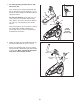
3. Identify the Right and Left Stabilizer Covers (12, 13), which are marked with “R” and “L” stickers. 3 Attach each Stabilizer Cover (12, 13) to the Rear Stabilizer (2) with two M4 x 16mm Screws (62). 62 62 13 2 62 12 62 4. Identify the Top Shield (14) and the Upright (4). 4 With the help of another person, slide the Top Shield (14) upward onto the Upright (4). Make sure that the Top Shield and the Upright are oriented as shown.
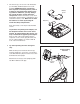
5. Tip: Avoid pinching the Wire Harness (40) during this step. 5 Have another person hold the Upright (4) and the Top Shield (14) near the Frame (1). Locate the wire tie in the Upright and the Wire Harness (40) in the Frame. Wire Tie 54 54 14 See the inset drawing. Tie the wire tie to one of the connectors on the Wire Harness (40). Then, pull the other end of the wire tie upward out of the top of the Upright (4). Discard the wire tie. 54 4 40 Wire Tie Slide the Upright (4) onto the Frame (1).
7. The Console (5) can use four 1.5V D batteries (not included); alkaline batteries are recommended. IMPORTANT: If the Console has been exposed to cold temperatures, allow it to warm to room temperature before inserting batteries. Otherwise, you may damage the console displays or other electronic components. Remove the battery cover, insert the batteries into the battery compartments, and reattach the battery cover. Make sure to orient the batteries as shown by the diagram inside the battery compartments.
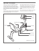
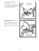
9. Tip: Avoid pinching the Pulse Wire (38) during this step. Orient the Pulse Bar (7) as shown. Attach the Pulse Bar to the Seat Carriage (6) with two M10 x 36mm Screws (57) and two M10 Locknuts (58). Do not tighten the Screws yet. 9 Avoid pinching the Pulse Wire (38) 7 38 58 6 57 57 10. Tip: Avoid pinching the Pulse Wire (not shown) during this step. Attach the Backrest (8) to the Seat Carriage (6) with two M6 x 18mm Patch Screws (59) and two M6 x 42mm Patch Screws (60). 10 59 8 See step 9.
. Orient the Seat (9) as shown. Attach the Seat to the Seat Carriage (6) with four 1/4" x 38mm Patch Screws (61) and four M6 Washers (63). Note: The Patch Screws and the Washers may be preattached to the underside of the Seat. 11 9 6 63 61 12. Attach the Pulse Bar Cover (15) to the Seat Carriage (6) with two M4 x 16mm Screws (62).
13. Plug the Pulse Wire (38) into the Pulse Receptacle (39) in the Frame (1). 13 38 39 14. Identify the Right Pedal (44), which is marked with an “R.” Using an adjustable wrench, firmly tighten the Right Pedal clockwise into the right side of the Crank (17). 1 14 Tighten the Left Pedal (not shown) counterclockwise into the left side of the Crank. Adjust the strap on the Right Pedal (44) to the desired position, and press the ends of the straps onto the tabs on the Right Pedal.
HOW TO USE THE EXERCISE BIKE HOW TO ADJUST THE PEDAL STRAPS To adjust the pedal straps, first pull the ends of the straps off the tabs on the pedals. Adjust the straps to the desired position, and then press the ends of the straps onto the tabs. HOW TO MOVE THE EXERCISE BIKE To move the exercise bike, lift the rear stabilizer until the exercise bike can be moved on the front wheels. Carefully move the exercise bike to the desired location and then lower it to the floor.
CONSOLE DIAGRAM FEATURES OF THE CONSOLE The console also features the new iFit interactive workout system. The iFit interactive workout system enables the console to accept iFit cards containing workouts designed to help you achieve specific fitness goals. The advanced console offers an array of features designed to make your workouts more effective and enjoyable. When you select the manual mode of the console, you can change the resistance of the pedals with a touch of the dial.
HOW TO USE THE MANUAL MODE The third section of the display will show the approximate number of calories you have burned and the resistance level of the pedals. The display will change modes every few seconds. The display will also show your heart rate when you use the handgrip pulse sensor (see step 5 below). 1. Turn on the console. To turn on the console, press any button or begin pedaling. The display will light and the console will be ready for use. 2. Select the manual mode.
HOW TO USE A TRAINER WORKOUT As you exercise, the display will prompt you to keep your pedaling pace near the pace setting for the current segment. When the word “faster” appears in the display, increase your pace. When the word “slower” appears, decrease your pace. When the center of the target flashes, maintain your current pace. 1. Turn on the console. To turn on the console, press any button or begin pedaling. The display will light and the console will be ready for use. 2. Select a trainer workout.
HOW TO USE A CALORIE GOAL WORKOUT As you exercise, the display will prompt you to keep your pedaling pace near the pace setting for the current segment. When the word “faster” appears in the display, increase your pace. When the word “slower” appears, decrease your pace. When the center of the target flashes, maintain your current pace. 1. Turn on the console. To turn on the console, press any button or begin pedaling. The display will light and the console will be ready for use. 2.
HOW TO USE AN IFIT WORKOUT THE INFORMATION MODE 1. Press any button on the console or begin pedaling to turn on the console. The console features an information mode that allows you to select a unit of measurement for the console and to view usage information for the exercise bike. When you turn on the console, the display will light. A tone will then sound and the console will be ready for use. To select the information mode, press and hold down the Workout button for a few seconds. 2.
MAINTENANCE AND TROUBLESHOOTING Inspect and tighten all parts of the exercise bike regularly. To clean the exercise bike, use a damp cloth and a small amount of mild detergent; never use abrasives or solvents to clean the exercise bike. To avoid damaging the console, keep liquid away from the console. Slide the Reed Switch (24) slightly closer to or away from the Magnet (50), and then retighten the M4 x 16mm Screw (62). Turn the Crank (17) for a moment.
EXERCISE GUIDELINES WARNING: Burning Fat—To burn fat effectively, you must exercise at a low intensity level for a sustained period of time. During the first few minutes of exercise, your body uses carbohydrate calories for energy. Only after the first few minutes of exercise does your body begin to use stored fat calories for energy. If your goal is to burn fat, adjust the intensity of your exercise until your heart rate is near the lowest number in your training zone.
PART LIST Key No. Qty. 1 2 3 4 5 6 7 8 9 10 11 12 13 14 15 16 17 18 19 20 21 22 23 24 25 26 27 28 29 30 31 32 33 34 35 36 37 38 39 40 1 1 1 1 1 1 1 1 1 1 1 1 1 1 1 1 1 1 1 1 1 1 1 1 1 1 1 1 1 2 2 2 2 4 2 4 4 1 1 1 Description Key No. Qty.
72 64 72 62 57 64 57 7 35 36 37 63 63 53 64 58 63 61 33 32 34 34 64 6 58 63 63 63 9 72 72 64 64 31 63 53 72 27 63 35 37 36 70 72 26 8 38 29 60 59 25 40 59 60 30 56 15 5 39 55 54 4 14 54 56 54 30 62 54 28 55 EXPLODED DRAWING A Model No. 831.21752.
62 23 42 62 13 62 62 45 52 62 43 11 73 42 2 62 45 51 16 58 65 62 12 62 62 43 66 22 49 20 21 1 62 18 68 71 69 46 67 23 17 19 50 21 24 41 50 62 3 62 62 41 48 62 10 46 44 44 47 EXPLODED DRAWING B Model No. 831.21752.
Get it fixed, at your home or ours! Your Home For repair—in your home—of all major brand appliances, lawn and garden equipment, or heating and cooling systems, no matter who made it, no matter who sold it! For the replacement parts, accessories, and user’s manuals that you need to do-it-yourself. For Sears professional installation of home appliances and items like garage door openers and water heaters. 1-800-4-MY-HOME® (1-800-469-4663) Call anytime, day or night (U.S.A. and Canada) www.sears.com www.