www.proform.com Model No. PFEL07909.4 Serial No. Write the serial number in the space above for reference. Serial Number Decal (on underside of frame) ACTIVATE YOUR WARRANTY To register your product and activate your warranty today, go to www.proformservice.com/ registration. CUSTOMER CARE For service at any time, go to www.proformservice.com. Or call 1-888-533-1333 Mon.–Fri. 6 a.m.–6 p.m. MT Sat. 8 a.m.–4 p.m. MT Please do not contact the store.
TABLE OF CONTENTS WARNING DECAL PLACEMENT . . . . . . . . . . . . . . . . . . . . . . . . . . . . . . . . . . . . . . . . . . . . . . . . . . . . . . . . . . . . . . . 2 IMPORTANT PRECAUTIONS . . . . . . . . . . . . . . . . . . . . . . . . . . . . . . . . . . . . . . . . . . . . . . . . . . . . . . . . . . . . . . . . . . 3 BEFORE YOU BEGIN. . . . . . . . . . . . . . . . . . . . . . . . . . . . . . . . . . . . . . . . . . . . . . . . . . . . . . . . . . . . . . . . . . . . . . . .
IMPORTANT PRECAUTIONS WARNING: To reduce the risk of burns, fire, electric shock, or injury to persons, read all important precautions and instructions in this manual and all warnings on your elliptical before using your elliptical. ICON assumes no responsibility for personal injury or property damage sustained by or through the use of this product. 1. It is the responsibility of the owner to ensure that all users of the elliptical are adequately informed of all precautions. 11.
STANDARD SERVICE PLANS all 4
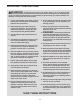
BEFORE YOU BEGIN Thank you for selecting the revolutionary PROFORM® 790 E elliptical. The 790 E elliptical provides an impressive selection of features designed to make your workouts at home more effective and enjoyable. manual. To help us assist you, note the product model number and serial number before contacting us. The model number and the location of the serial number decal are shown on the front cover of this manual. For your benefit, read this manual carefully before you use the elliptical.
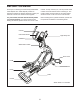
PART IDENTIFICATION CHART Use the drawings below to identify the small parts needed for assembly. The number in parentheses below each drawing is the key number of the part, from the PART LIST near the end of this manual. The number following the key number is the quantity needed for assembly. Note: If a part is not in the hardware kit, check to see if it has been preassembled. Extra parts may be included.
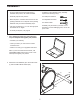
ASSEMBLY • To hire an authorized service technician to assemble this product, call 1-800-445-2480. • In addition to the included tool(s), assembly requires the following tool(s): • Assembly requires two persons. one Phillips screwdriver • Place all parts in a cleared area and remove the packing materials. Do not dispose of the packing materials until you nish all assembly steps. two adjustable wrenches • Left parts are marked “L” or “Left” and right parts are marked “R” or “Right.
3. Orient the Rear Stabilizer (62) and the Rear Frame (2) as shown. 3 Tip: If the Ramp Cover (see step 16) is attached to the Ramp (3), remove the Ramp Cover. 3 62 Attach the Rear Stabilizer (62) to the Rear Frame (2) with two M8 x 56mm Screws (94) and two M8 Split Washers (83). 2 94 4. Insert the Rear Frame (2) into the Front Frame (1); make sure that the Ramp (3) is on the Lift Roller (12). 83 4 Attach the Rear Frame (2) with five M8 x 19mm Screws (82) and five M8 Split Washers (83).
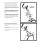
5. Have a second person orient the Upright (4) as shown and hold it near the Front Frame (1). 5 Locate the wire tie in the Upright (4). Tie the lower end of the wire tie to the Upper Wire Harness (110). Next, pull the upper end of the wire tie until the Upper Wire Harness is routed xthrough the Upright. Then, untie and discard the wire tie.
7. Identify the Right Upper Body Arm (61) and the Right Upper Body Leg (60) and orient them as shown. Make sure that the hexagonal holes are in the position shown. 7 Slide the Right Upper Body Arm (61) onto the Right Upper Body Leg (60). Attach the Right Upper Body Arm with two M8 x 38mm Bolts (96) and two M8 Locknuts (102). Make sure that the Locknuts are in the hexagonal holes. 102 61 Hexagonal Holes Repeat this step for the Left Upper Body Arm (not shown) and the Left Upper Body Leg (not shown).
9. Attach an Outer Cover (67) to the Inner Cover (68) on the Right Upper Body Leg (60) with two M4 x 16mm Screws (104). 9 Repeat this step on the other side of the elliptical. 104 68 67 104 60 10. Have a second person hold the Console (7) near the Upright (4). 10 Avoid pinching the wires 7 Connect the wires on the Console (7) to the Ground Wire (120), to the Pulse Wires (63, 69), and to the Upper Wire Harness (110). 63 120 Insert the excess wires into the Upright (4).
11. Orient the Rear Upright Cover (80) as shown. 11 Attach the Rear Upright Cover (80) to the Upright (4) with two M4 x 16mm Screws (104). 104 4 80 12. Orient the Front Upright Cover (91) as shown. 12 Attach the Front Upright Cover (91) around the Upright (4) by pressing the tabs on the Front Upright Cover into the Rear Upright Cover (80).
. Apply a small amount of grease to the right Crank Arm (20). 13 Orient a Roller Arm (45) so that the Roller (51) is in the position shown. Slide the Roller Arm (45) onto the right Crank Arm (20) while setting the Roller (51) on the Ramp (3). 20 Grease 98 53 Attach the Roller Arm (45) with an M8 x 19mm Screw (82), an Axle Cover (53), and an M8 x 25mm Washer (98); to avoid breaking the Axle Cover, do not overtighten the Screw. 82 45 Repeat this step on the other side of the elliptical. 51 3 14.
15. See the upper drawing. Apply a small amount of grease to the axle on the Right Upper Body Leg (60) and to the axle on the Right Pedal Arm (58). 15 60 Grease Orient the Right Pedal Arm (58) as shown. Slide the Right Pedal Arm onto the Right Upper Body Leg (60) and into the right Roller Arm (45) at the same time.
HOW TO USE THE ELLIPTICAL HOW TO PLUG IN THE POWER CORD A temporary adapter may be used to connect the power cord to a 2-pole receptacle as shown at the right if a properly grounded outlet is not available. This product must be grounded. If it should malfunction or break down, grounding provides a path of least resistance for electric current to reduce the risk of electric shock. The power cord has a plug with a grounding pin.
HOW TO MOVE THE ELLIPTICAL HOW TO EXERCISE ON THE ELLIPTICAL Due to the size and weight of the elliptical exerciser, moving it requires two persons. Stand in front of the elliptical, hold the upright, and place one foot against one of the front wheels. Pull on the upright and have a second person lift the handle at the rear until the elliptical will roll on the front wheels. Carefully move the elliptical to the desired location, and then lower it to the floor.
CONSOLE DIAGRAM FEATURES OF THE CONSOLE For example, lose unwanted pounds with the 8-week Weight Loss workout. iFit workouts control the resistance of the pedals while the voice of a personal trainer coaches you through your workouts. iFit cards are available separately. To purchase iFit cards, go to www.iFit.com or see the front cover of this manual. iFit cards are also available at select stores.
HOW TO TURN ON THE POWER 3. Change the resistance of the pedals and the incline of the ramp as desired. IMPORTANT: If the elliptical has been exposed to cold temperatures, allow it to warm to room temperature before turning on the power. If you do not do this, you may damage the console displays or other electrical components. Plug in the power cord (see HOW TO PLUG IN THE POWER CORD on page 15). Next, locate the power switch on the frame near the power cord.
The upper display—This display can show the elapsed time, the distance that you have pedaled, your pedaling speed, and the approximate number of calories you have burned. When your pulse is detected, a flashing heart symbol will appear in the display, and then your heart rate will appear. For the most accurate heart rate reading, hold the contacts for at least 15 seconds. Note: If you continue to hold the handgrip heart rate monitor, the display will show your heart rate for up to 30 seconds.
HOW TO USE A PRESET WORKOUT As you exercise, keep your pedaling speed near the target speed for the current segment. At the beginning of each segment, the target speed for the segment will flash in the display. 1. Begin pedaling or press any button on the console to turn on the console. See HOW TO TURN ON THE POWER on page 18. 2. Select a preset workout.
HOW TO USE AN IFIT WORKOUT HOW TO USE THE SOUND SYSTEM iFit cards are available separately. To purchase iFit cards, go to www.iFit.com or see the front cover of this manual. iFit cards are also available at select stores. To play music or audio books through the console sound system while you exercise, plug your audio cable into the jack on the console and into a jack on your MP3 player or CD player; make sure that your audio cable is fully plugged in. 1.
MAINTENANCE AND TROUBLESHOOTING Inspect and tighten all parts of the elliptical regularly. Replace any worn parts immediately. HOW TO ADJUST THE DRIVE BELT If the pedals slip while you are pedaling, even while the resistance is adjusted to the highest level, the drive belt may need to be adjusted. To clean the elliptical, use a damp cloth and a small amount of mild soap. IMPORTANT: To avoid damage to the console, keep liquids away from the console and keep the console out of direct sunlight.
HOW TO ADJUST THE REED SWITCH Locate the Reed Switch (38). Rotate the Pulley (19) until a Magnet (43) is aligned with the Reed Switch. Next, loosen but do not remove the indicated M4 x 16mm Screw (104). Slide the Reed Switch slightly closer to or away from the Magnet. Then, retighten the Screw. Turn the Pulley for a moment. Repeat until the console displays correct feedback. If the console does not display correct feedback, the reed switch should be adjusted.
EXERCISE GUIDELINES Burning Fat—To burn fat effectively, you must exercise at a low intensity level for a sustained period of time. During the first few minutes of exercise, your body uses carbohydrate calories for energy. Only after the first few minutes of exercise does your body begin to use stored fat calories for energy. If your goal is to burn fat, adjust the intensity of your exercise until your heart rate is near the lowest number in your training zone.
SUGGESTED STRETCHES The correct form for several basic stretches is shown at the right. Move slowly as you stretch; never bounce. 1. Toe Touch Stretch Stand with your knees bent slightly and slowly bend forward from your hips. Allow your back and shoulders to relax as you reach down toward your toes as far as possible. Hold for 15 counts, then relax. Repeat 3 times. Stretches: Hamstrings, back of knees and back. 1 2. Hamstring Stretch Sit with one leg extended.
NOTES 26
PART LIST Key No. Qty. 1 2 3 4 5 6 7 8 9 10 11 12 13 14 15 16 17 18 19 20 21 22 23 24 25 26 27 28 29 30 31 32 33 34 35 36 37 38 39 40 41 42 43 44 45 46 47 48 49 50 51 1 1 1 1 1 1 1 1 1 1 1 1 1 1 1 1 1 1 1 2 1 1 1 1 1 1 1 1 1 8 1 1 1 2 1 4 1 1 1 2 1 2 2 1 2 1 1 1 2 2 2 Model No. PFEL07909.4 R1212A Description Key No. Qty.
Key No. Qty. 103 104 105 106 107 108 109 110 111 112 113 1 35 1 3 4 2 3 1 12 1 1 Description Key No. Qty. M3.5 x 12mm Flat Head Screw M4 x 16mm Screw Lower Wire Harness M4 x 16mm Bright Screw Roller Arm Bushing M6 x 13mm Screw M6 Washer Upper Wire Harness M6 Split Washer Power Cord Drive Belt 114 115 116 117 118 119 120 * * * 6 4 2 6 2 3 1 – – – Description M6 x 25mm Flat Head Screw #6 x 9.
94 66 36 92 104 65 104 83 72 72 117 92 62 3 85 33 23 83 104 115 93 79 1 40 5 100 64 104 88 106 22 82 24 118 103 83 42 27 97 15 26 25 9 102 28 82 98 30 115 105 119 110 90 29 99 82 30 55 8 13 86 12 102 11 30 56 54 20 102 78 112 2 109 117 72 36 66 72 10 32 108 17 104 30 77 31 82 87 43 34 113 98 43 16 39 106 42 104 81 104 109 101 21 89 99 40 38 14 19 6 102 18 84 81 20 108 86 85 78 109 34 EXPLODED DRAWING A
59 111 52 48 104 47 82 53 111 49 59 96 72 51 36 53 66 98 98 67 119 72 44 82 82 102 104 7 45 57 98 46 107 116 37 35 69 57 107 119 80 104 104 51 53 68 30 52 53 72 95 41 66 36 82 104 70 82 83 82 83 104 104 104 106 120 82 96 72 104 61 82 104 30 95 70 4 104 45 102 107 60 63 104 104 68 91 82 53 58 107 98 53 111 82 98 116 49 98 53 57 82 59 111 82 57 67 EXPLODED DRAWING B Model No. PFEL07909.
71 76 114 76 104 114 76 114 73 75 50 104 76 76 104 74 76 76 104 104 104 76 31 114 114 76 50 76 114 71 EXPLODED DRAWING C Model No. PFEL07909.
ORDERING REPLACEMENT PARTS To order replacement parts, please see the front cover of this manual.