Model No. PETL80711.0 Serial No. Write the serial number in the space above for reference. USER’S MANUAL Serial Number Decal QUESTIONS? If you have questions, or if there are missing parts, please contact us: UNITED KINGDOM Call: 08457 089 009 From Ireland: 053 92 36102 Website: www.iconsupport.eu E-mail: csuk@iconeurope.com Write: ICON Health & Fitness, Ltd. c/o HI Group PLC Express Way CASTLEFORD WF10 5QJ UNITED KINGDOM AUSTRALIA Call: 1800 993 770 E-mail: australiacc@iconfitness.
TABLE OF CONTENTS WARNING DECAL PLACEMENT . . . . . . . . . . . . . . . . . . . . . . . . . . . . . . . . . . . . . . . . . . . . . . . . . . . . . . . . . . . . . . .2 IMPORTANT PRECAUTIONS. . . . . . . . . . . . . . . . . . . . . . . . . . . . . . . . . . . . . . . . . . . . . . . . . . . . . . . . . . . . . . . . . . 3 BEFORE YOU BEGIN. . . . . . . . . . . . . . . . . . . . . . . . . . . . . . . . . . . . . . . . . . . . . . . . . . . . . . . . . . . . . . . . . . . . . . . .5 PART IDENTIFICATION CHART.
IMPORTANT PRECAUTIONS WARNING: To reduce the risk of serious injury, read all important precautions and instructions in this manual and all warnings on your treadmill before using your treadmill. ICON assumes no responsibility for personal injury or property damage sustained by or through the use of this product. 1. Before beginning any exercise program, consult your physician. This is especially important for persons over age 35 or persons with pre-existing health problems. circuit.
20. Do not attempt to move the treadmill until it is properly assembled. (See ASSEMBLY on page 7, and HOW TO FOLD AND MOVE THE TREADMILL on page 22.) You must be able to safely lift 45 lbs. (20 kg) to move the treadmill. the treadmill, and before performing the maintenance and adjustment procedures described in this manual. Never remove the motor hood unless instructed to do so by an authorized service representative.
BEFORE YOU BEGIN Thank you for selecting the new PROFORM® 720 ZLT treadmill. The PROFORM 720 ZLT treadmill provides an impressive selection of features designed to make your workouts at home more effective and enjoyable. manual. To help us assist you, note the product model number and serial number before contacting us. The model number and the location of the serial number decal are shown on the front cover of this manual. For your benefit, read this manual carefully before you use the treadmill.
PART IDENTIFICATION CHART Use the drawings below to identify small parts used for assembly. The number in parentheses below each drawing is the key number of the part, from the PART LIST near the end of this manual. The number following the key number is the quantity used for assembly. Note: If a part is not in the hardware kit, check to see if it is preattached. Extra hardware may be included.
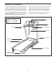
ASSEMBLY • Assembly requires two persons. • Assembly requires the following tools: • Place all parts in a cleared area and remove the packing materials. Do not dispose of the packing materials until you finish all assembly steps. the included hex keys • After shipping, there may be an oily substance on the exterior of the treadmill. This is normal. If there is an oily substance on the treadmill, wipe it off with a soft cloth and a mild, non-abrasive cleaner.
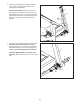
2. Identify the Left Upright (75), which is marked “Left.” Have a second person hold the Left Upright near the Base (80). 2 70 See the inset drawing. Tie the wire tie in the Left Upright (75) securely around the end of the Upright Wire (70). Then, insert the Upright Wire into the lower end of the Left Upright as you pull the other end of the wire tie through the Left Upright. 75 Wire Tie 75 70 80 Wire Tie 3. Hold the Left Upright (75) against the Base (80). Be careful not to pinch the wires.
4. Identify the Left Handrail (71), which is marked “Left.” Remove the tie from the 5/16" Cage Nut (33). If necessary, press the Cage Nut back into place. 4 Tie 70 Hold the Left Handrail (71) near the Left Upright (75). Insert the Upright Wire (70) through the bracket on the bottom of the Left Handrail. Then, pull the Upright Wire out of the end of the Handrail.
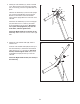
6. With the help of a second person, hold the console assembly near the Left Upright (75). 6 Console Assembly Connect the Upright Wire (70) to the console wire. See the inset drawing. The connectors should slide together easily and snap into place. If they do not, turn one connector and try again. IF YOU DO NOT CONNECT THE CONNECTORS PROPERLY, THE CONSOLE MAY BECOME DAMAGED WHEN YOU TURN ON THE POWER. 70 Remove the wire tie from the Upright Wire (70). Console Wire 75 Console Wire Wire Tie 70 7.
8. Attach the console assembly to the Left Handrail Tube (98) and the Right Handrail Tube (99) with four #8 x 3/4" Screws (6); start all four Screws, and then tighten them. Do not overtighten the Screws. 8 Console Assembly 99 98 6 6 9. Identify the Left Tray (87) and the Right Tray (88). Make sure that the indicated notch is positioned as shown. Attach the Trays with eight #8 x 3/4" Screws (6). Start all eight Screws, and then tighten them. Do not overtighten the Screws.
10. Fully tighten the six 3/8" x 3 1/2" Screws (4) (three on each side). 10 4 4 11. Raise the Frame (49) to the position shown. Have a second person hold the Frame until this step is completed. 11 Orient the Storage Latch (51) so that the large barrel and the latch knob are oriented as shown. 49 Attach the lower end of the Storage Latch (51) to the Base (80) with a 3/8" x 2" Bolt (13) and a 3/8" Nut (3). 3 .
SP OPERATION AND ADJUSTMENT HOW TO PLUG IN THE POWER CORD Follow the steps below to plug in the power cord. This product must be earthed. If it should malfunction or break down, earthing provides a path of least resistance for electric current to reduce the risk of electric shock. This product’s power cord has an equipment-earthing conductor and an earthing plug. IMPORTANT: If the power cord is damaged, it must be replaced with a manufacturer-recommended power cord. 1.
CONSOLE DIAGRAM FEATURES OF THE CONSOLE You can even listen to your favorite workout music or audio books with the console’s premium stereo sound system while you get in shape. The treadmill console offers an impressive array of features designed to make your workouts more effective and enjoyable. To turn on the power, see page 15. To use the manual mode, see page 15. To use a weight-loss workout, see page 18. To use an iFit Live workout, see page 19. To use the cool-down mode, see page 20.
HOW TO TURN ON THE POWER HOW TO USE THE MANUAL MODE IMPORTANT: If the treadmill has been exposed to cold temperatures, allow it to warm to room temperature before you turn on the power. If you do not do this, you may damage the console displays or other electrical components. 1. Insert the key into the console. Plug in the power cord (see page 13). Next, locate the power switch on the treadmill frame near the power cord. Make sure that the switch is in the reset position.
4. Change the incline of the treadmill as desired. The My Trail tab will show a track that represents 400 m (1/4 mile). As you exercise, the flashing rectangle will show your progress. The My Trail tab will also show the number of laps you complete. To change the incline of the treadmill, press the Incline increase or decrease button or one of the numbered Quick Incline buttons. Each time you press one of the buttons, the treadmill will gradually adjust to the selected incline setting.
6. Measure your heart rate if desired. dashes will appear, and then your heart rate will be shown. For the most accurate heart rate reading, continue to hold the contacts for about 15 seconds. Note: If you use the handgrip heart rate monitor and the chest heart rate monitor at the same time, the console will not display your heart rate accurately. For information about the optional chest heart rate monitor, see page 20. 7. When you are finished exercising, remove the key from the console.
HOW TO USE A WEIGHT-LOSS WORKOUT Each workout is divided into one-minute segments. One speed setting and one incline setting are programmed for each segment. Note: The same speed setting and/or incline setting may be programmed for consecutive segments. 1. Insert the key into the console. See HOW TO TURN ON THE POWER on page 15. 2. Select a time for the workout. At the end of each segment, a series of tones will sound.
HOW TO USE AN IFIT LIVE WORKOUT When you select an iFit Live workout, the display will show the duration of the workout, the distance you will walk or run, and the approximate number of calories you will burn. The display may also show the name of the workout. If you select a competition workout, the display will count down to the beginning of the race. Note: To use an iFit Live workout, you must have an optional iFit Live module. To purchase an iFit Live module at any time, go to www.iFit.
6. Follow your progress with the displays. To use the audio jack, plug your audio wire into the audio jack below the Cool Down button. Then, plug your audio wire into a jack on your MP3 player, CD player, or other personal audio player. Make sure that your audio wire is fully plugged in. See step 5 on page 16. The My Trail tab will show a map of the trail you are walking or running or it will show a track and the number of laps you complete.
THE INFORMATION MODE console. However, when you remove the key, the displays will remain lit, although the buttons will not function. If the demo mode is turned on, the word ON will appear in the matrix. To turn on or turn off the demo mode, press the Enter button. The console features an information mode that keeps track of treadmill information and allows you to personalize console settings. 1. Select the information mode. c.
HOW TO FOLD AND MOVE THE TREADMILL HOW TO FOLD THE TREADMILL HOW TO MOVE THE TREADMILL To avoid damaging the treadmill, adjust the incline to the lowest position before you fold the treadmill. Then, remove the key and unplug the power cord. CAUTION: You must be able to safely lift 45 lbs. (20 kg) to raise, lower, or move the treadmill. efore moving the treadmill, fold it as described at the B left. CAUTION: Make sure that the latch knob is locked in the storage position.
TROUBLESHOOTING Most treadmill problems can be solved by following the simple steps below. Find the symptom that applies, and follow the steps listed. If further assistance is needed, see the front cover of this manual. b. Make sure that the power cord is plugged in. If the power cord is plugged in, unplug it, wait for five minutes, and then plug it back in. c. Remove the key from the console, and then reinsert it. SYMPTOM: The power does not turn on a.
Lower the treadmill (see HOW TO LOWER THE TREADMILL FOR USE on page 22). Remove the three #8 x 3/4" Screws (6). Carefully slide the Motor Hood (57) off. This will recalibrate the incline system. If the incline does not begin calibrating, press the Stop button again, and then press the Incline increase or decrease button again. When the incline is calibrated, remove the key from the console. SYMPTOM: The walking belt slows when walked on 57 6 a.
SYMPTOM: The walking belt is not centered between the foot rails. IMPORTANT: If the walking belt rubs against the foot rails, the walking belt may be damaged. SYMPTOM: The walking belt slips when walked on a. F irst, remove the key and UNPLUG THE POWER CORD. Using the hex key, turn both idler roller screws clockwise, 1/4 of a turn. When the walking belt is correctly tightened, you should be able to lift each edge of the walking belt 2 to 3 in. (5 to 7 cm) off the walking platform.
EXERCISE GUIDELINES Burning Fat—To burn fat effectively, you must exercise at a low intensity level for a sustained period of time. During the first few minutes of exercise, your body uses carbohydrate calories for energy. Only after the first few minutes of exercise does your body begin to use stored fat calories for energy. If your goal is to burn fat, adjust the intensity of your exercise until your heart rate is near the lowest number in your training zone.
PART LIST Key No. Qty. 1 2 3 4 5 6 7 8 9 10 11 12 13 14 15 16 17 18 19 20 21 22 23 24 25 26 27 28 29 30 31 32 33 34 35 36 37 38 39 40 41 42 43 44 45 46 47 48 49 50 51 52 53 11 2 6 6 6 49 8 8 4 2 1 1 1 2 2 2 2 3 17 2 2 2 2 8 2 1 2 2 4 1 1 1 2 1 1 2 1 1 1 1 2 2 1 1 1 1 1 2 1 1 1 1 1 Model No. PETL80711.0 R0412A Description Key No. Qty.
34 19 14 29 19 35 25 56 19 24 36 19 38 53 24 39 19 52 14 19 25 19 19 37 40 41 24 29 19 19 42 28 3 19 19 29 27 23 12 36 24 44 43 95 45 19 24 10 16 1 19 51 46 11 24 48 19 41 47 27 42 28 29 31 32 3 48 26 49 13 50 1 16 85 1 EXPLODED DRAWING A Model No. PETL80711.
EXPLODED DRAWING B Model No. PETL80711.
EXPLODED DRAWING C Model No. PETL80711.
EXPLODED DRAWING D Model No. PETL80711.
ORDERING REPLACEMENT PARTS To order replacement parts, please see the front cover of this manual.