Model No. PFEVEX72913.0 Serial No. Write the serial number in the space above for reference. USER’S MANUAL Serial Number Decal (under frame) CUSTOMER SERVICE UNITED KINGDOM Call: 08457 089 009 From Ireland: 053 92 36102 Website: www.iconsupport.eu E-mail: csuk@iconeurope.com Write: ICON Health & Fitness, Ltd. c/o HI Group PLC Express Way CASTLEFORD WF10 5QJ UNITED KINGDOM AUSTRALIA Call: 1800 993 770 E-mail: australiacc@iconfitness.
TABLE OF CONTENTS WARNING DECAL PLACEMENT . . . . . . . . . . . . . . . . . . . . . . . . . . . . . . . . . . . . . . . . . . . . . . . . . . . . . . . . . . . . . . .2 IMPORTANT PRECAUTIONS. . . . . . . . . . . . . . . . . . . . . . . . . . . . . . . . . . . . . . . . . . . . . . . . . . . . . . . . . . . . . . . . . . 3 BEFORE YOU BEGIN. . . . . . . . . . . . . . . . . . . . . . . . . . . . . . . . . . . . . . . . . . . . . . . . . . . . . . . . . . . . . . . . . . . . . . . .4 PART IDENTIFICATION CHART.
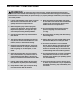
IMPORTANT PRECAUTIONS WARNING: To reduce the risk of serious injury, read all important precautions and instructions in this manual and all warnings on your exercise bike before using your exercise bike. ICON assumes no responsibility for personal injury or property damage sustained by or through the use of this product. 1. It is the responsibility of the owner to ensure that all users of the exercise bike are adequately informed of all precautions. 9.
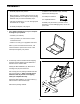
BEFORE YOU BEGIN Thank you for selecting the new PROFORM® 245 ZLX exercise bike. Cycling is an effective exercise for increasing cardiovascular fitness, building endurance, and toning the body. The 245 ZLX exercise bike provides an impressive selection of features designed to make your workouts at home more effective and enjoyable. reading this manual, please see the front cover of this manual. To help us assist you, note the product model number and serial number before contacting us.
PART IDENTIFICATION CHART Use the drawings below to identify the small parts needed for assembly. The number in parentheses below each drawing is the key number of the part, from the PART LIST near the end of this manual. The number following the key number is the quantity needed for assembly. Note: If a part is not in the hardware kit, check to see if it has been preassembled. Extra parts may be included.
ASSEMBLY • Assembly requires two persons. • In addition to the included tool(s), assembly requires the following tools: • Place all parts in a cleared area and remove the packing materials. Do not dispose of the packing materials until you finish all assembly steps. one Phillips screwdriver one adjustable wrench • Left parts are marked “L” or “Left” and right parts are marked “R” or “Right.” Assembly may be easier if you have a set of wrenches. To avoid damaging parts, do not use power tools.
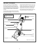
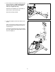
3. Set a sturdy piece of packing material under the front of the Frame (1). Have a second person hold the Frame to prevent it from tipping while you complete this step. 3 Attach the Front Stabilizer (2) to the Frame (1) with two M10 x 75mm Screws (36). 2 Remove the packing material. 36 1 4. Orient the Upright (3) and the Top Shield (9) as shown. 4 Have a second person hold the Upright (3) and the Top Shield (9) near the Frame (1) until you complete step 4.
5. Tip: Avoid pinching the wires. Slide the Upright (3) onto the Frame (1). 5 Attach the Upright (3) with four M8 x 18mm Screws (35). Avoid pinching the wires Slide the Top Shield (9) downward and press it onto the Left and Right Shields (17, 18). 3 9 35 35 17 1 18 6. See the inset drawing. Remove the Seat Knob (8) from the Seat Carriage (56). Next, attach the Seat (12) to the Seat Carriage (56) with four M8 Locknuts (37). Note: The Locknuts may be preattached to the underside of the Seat.
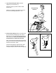
7. Using an adjustable wrench, tighten the Post Knob (11) into the Frame (1). 7 Next, loosen the Post Knob (11) a few turns, pull it outward, and insert the Seat Post (5) into the Frame (1). Slide the Seat Post (5) upward or downward to the desired position, and release the Post Knob (11) into one of the adjustment holes in the Seat Post. Move the Seat Post upward or downward slightly to make sure that the Post Knob is engaged in one of the adjustment holes in the Seat Post. Then, tighten the Post Knob.
9. Identify the Right Handlebar (48) and orient it as shown. 9 While a second person holds the Right Handlebar (48) near the Upright (3), tie the indicated wire tie to the Right Pulse Wire (42). Then, pull the other end of the wire tie upward out of the top of the Upright. Avoid pinching the wire 47 28 Tip: Avoid pinching the wire. Slide the Right Handlebar (48) onto the Upright (3). Wire Tie 42 53 3 Attach the Right Handlebar (48) with two M8 x 38mm Bolts (53) and two M8 Locknuts (37).
. While a second person holds the Console (6) near the Upright (3), connect the wires on the Console to the Upper Wire (32) and to the Right and Left Pulse Wires (42, 28). 11 Avoid pinching the wire Insert the excess wire into the Upright (3) or into the Console (6). 6 Tip: Avoid pinching the wires. Attach the Console (6) to the Upright (3) with four M4 x 16mm Screws (40). 32 3 40 42 12. Attach the Handlebar Cover (19) to the Upright (3) with two M4 x 16mm Screws (40).
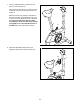
13. Identify the Right Pedal (26). 13 Using an adjustable wrench, firmly tighten the Right Pedal (26) clockwise into the Right Crank (58). Tighten the Left Pedal (not shown) counterclockwise into the Left Crank Arm (not shown). Adjust the strap on the Right Pedal (26) to the desired position, and press the end of the strap onto the tab on the Right Pedal. Adjust the strap on the Left Pedal (not shown) in the same way. 58 Strap 26 Tab 14.
HOW TO USE THE EXERCISE BIKE HOW TO ADJUST THE HEIGHT OF THE SEAT HOW TO ADJUST THE PEDAL STRAPS For effective exercise, the seat should be at the proper height. As you pedal, there should be a slight bend in your knees when the pedals are in the lowest position. To adjust the pedal straps, first pull the ends of the straps off the tabs on the pedals. Then, adjust the straps to the desired position, and press the ends of the straps onto the tabs.
CONSOLE DIAGRAM FEATURES OF THE CONSOLE resistance of the pedals as it guides you through an effective workout. The advanced console offers an array of features designed to make your workouts more effective and enjoyable. You can even connect your MP3 player or CD player to the console sound system and listen to your favorite music or audio books while you exercise. When you use the manual mode of the console, you can change the resistance of the pedals with the touch of a button.
HOW TO USE THE MANUAL MODE Note: During a preset workout, the display will show the time remaining in the workout. 1. Turn on the console. The left display will also show your heart rate when you use the handgrip heart rate monitor (see step 5). Press any button or begin pedaling to turn on the console. The center display– This display will show the resistance level of the pedals for a few seconds each time the resistance level changes.
3. Select the desired day of the program. When your pulse is detected, a heart-shaped symbol will flash in the display and then your heart rate will be shown. For the most accurate heart rate reading, hold the contacts for at least 15 seconds. There are three day workouts for each week of the program. To select the desired day of the program, press the Select Day button repeatedly until the number of the desired day appears in the display.
HOW TO USE A PRESET WORKOUT The target speed for the next segment will appear in the right display for a few seconds to alert you. 1. Turn on the console. As you exercise, keep your pedaling speed near the target speed for the current segment. IMPORTANT: The target speed is intended only to provide motivation. Your actual pedaling speed may be slower than the target speed. Make sure to pedal at a speed that is comfortable for you. Press any button or begin pedaling to turn on the console. 2.
HOW TO USE THE SOUND SYSTEM The resistance level for the next segment will appear in the center display for a few seconds to alert you. The resistance of the pedals will then change. To play music or audio books through the console sound system while you exercise, plug a 3.5 mm male to 3.5 mm male audio cable (not included) into the jack on the console and into a jack on your MP3 player, CD player, or other personal audio player; make sure that the audio cable is fully plugged in.
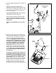
MAINTENANCE AND TROUBLESHOOTING Inspect and tighten all parts of the exercise bike regularly. Replace any worn parts immediately. Using a flat screwdriver, release the tabs along the bottom edge of the Top Shield (9) and slide the Top Shield upward. To clean the exercise bike, use a damp cloth and a small amount of mild soap. IMPORTANT: To avoid damage to the console, keep liquids away from the console and keep the console out of direct sunlight. Locate the Reed Switch (21).
HOW TO ADJUST THE DRIVE BELT Remove all the screws from the left and right shields; there are two sizes of screws in the shields—note which size of screw you remove from each hole. Then, gently pull the right shield away from the frame. If the pedals slip while you are pedaling, even while the resistance is adjusted to the highest level, the drive belt may need to be adjusted. Loosen the M6 x 20mm Hex Screw (46). Then, tighten the M10 x 50mm Hex Screw (33) until the Drive Belt (23) is tight.
EXERCISE GUIDELINES Burning Fat—To burn fat effectively, you must exercise at a low intensity level for a sustained period of time. During the first few minutes of exercise, your body uses carbohydrate calories for energy. Only after the first few minutes of exercise does your body begin to use stored fat calories for energy. If your goal is to burn fat, adjust the intensity of your exercise until your heart rate is near the lowest number in your training zone.
PART LIST Key No. Qty. 1 2 3 4 5 6 7 8 9 10 11 12 13 14 15 16 17 18 19 20 21 22 23 24 25 26 27 28 29 30 31 32 33 1 1 1 2 1 1 1 1 1 2 1 1 1 1 2 2 1 1 1 1 1 1 1 1 1 1 1 1 1 2 1 1 1 Model No. PFEVEX72913.0 R0713A Description Key No. Qty.
EXPLODED DRAWING Model No. PFEVEX72913.
ORDERING REPLACEMENT PARTS To order replacement parts, please see the front cover of this manual.