
User`s manual


236
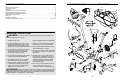
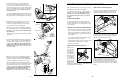
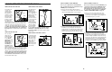
6. Whilst another person holds the Console (16) in the
position shown, connect the wire harness on the
Console to the Upper Wire Harness (36). Insert the
excess wire harness into the Upright (13).
Attach the Console (16) to the Upright (13) with three
M10 x 27mm Button Screws (51) and three M10 Black
Split Washers (50). Be careful to avoid pinching the
wire harnesses.
Snap the bookrack onto the Console (16) in the indicat-
ed location.
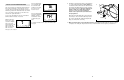
7. Turn the indicated Adjustment Knob (28) counterclock-
wise two or three turns to loosen it. Next, pull the Knob,
insert the Seat Post (5) into the Frame (1), and then
release the Knob. Move the Seat Post up and down
slightly until the pin on the Knob snaps into one of
the holes in the Seat Post. Then, turn the Knob clock-
wise until it is tight.
8. Attach the Seat (12) to the Seat Bracket (6) with four
M8 Nylon Locknuts (10) and four M8 Split Washers
(70). Note: The Nylon Locknuts and the Split Washers
may be pre-attached to the underside of the Seat.
Turn the Seat Adjustment Knob (9) counterclockwise
two or three turns to loosen it. Next, pull the Knob, slide
the Seat Bracket (6) into the top of the Seat Post (5),
and then release the Knob. Move the Seat Bracket
forward and backward slightly until the pin on the
Knob snaps into one of the holes in the Seat
Bracket. Then, turn the Knob clockwise until it is tight.
1
5
28
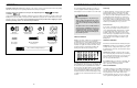
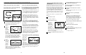
5. Connect the wire harness on the Handgrip Pulse
Sensor (15) to the indicated wire harness on the
Console (16). Insert both wire harnesses into the open-
ing in the bottom of the Console. Then, insert the metal
tube on the Handgrip Pulse Sensor into the opening in
the bottom of the console. Be careful not to pinch
the wire harnesses.
See the inset drawing. Tighten an M4 x 16mm Screw
(66) into the indicated bracket on the Console (16) and
into the metal tube on the Handgrip Pulse Sensor (15).
15
16
5
7
5
10
70
6
12
70
10
9
8
Metal Tube
15
16
66
Bracket
6
16
36
51
51
13
Wire Harness
Bookrack
50
50
51
MAINTENANCE AND TROUBLESHOOTING
Inspect and tighten all parts of the exercise cycle reg-
ularly. Replace any worn parts immediately.
To clean the exercise cycle, use a damp cloth and a
small amount of mild soap. Important: To avoid
damage to the console, keep liquids away from
the console and keep the console out of direct
sunlight.
BATTERY REPLACEMENT
If the console display becomes dim, the batteries
should be replaced; most console problems are the
result of low batteries. See assembly step 4 on page
5 for instructions.
HANDGRIP PULSE SENSOR TROUBLESHOOTING
• Avoid moving your hands whilst using the handgrip
pulse sensor. Excessive movement may interfere
with heart rate readings. Do not hold the metal con-
tacts too tightly; doing so may interfere with heart
rate readings.
• For the most accurate heart rate reading, hold the
metal contacts for about 15 seconds.
• Keep the metal contacts clean. The contacts can be
cleaned with a soft cloth—never use alcohol,
abrasives, or chemicals.
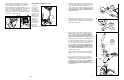
HOW TO LEVEL THE EXERCISE CYCLE
After the exer-
cise cycle has
been moved to
the location
where it will be
used, make sure
that both ends of
front stabiliser
are touching the
floor. If the exer-
cise cycle rocks
slightly during
use, turn one or
both of the levelling feet under the front stabiliser until
the rocking motion is eliminated.
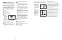
HOW TO ADJUST THE REED SWITCH
If the console does not display correct feedback, the
reed switch should be adjusted. To adjust the reed
switch, the Left Side Shield (17) must be removed.
Remove the seven Screws (52) from the Right Side
Shield (18). Next, remove the Screw (71) from the
right side of the Side Shield Cover (19).
Using an adjustable wrench, turn the Left Pedal (24)
clockwise and remove it. Next, remove the two
Screws (66) from the Left Side Shield (17). Remove
the Screw (71) from the left side of the Side Shield
Cover (19) and lift it off. Gently remove the Left Side
Shield.
52
71
18
19
52
66
71
17
24
19
Levelling
Foot
Avoid
pinching
the wire
harnesses.