Model No. 831.153321 Serial No. Write the serial number in the space above for reference. WEIGHT BENCH EXERCISER User’s Manual Serial Number Decal (under seat) • Assembly • Adjustments • Part List and Drawing Patent Pending CAUTION Read all precautions and instructions in this manual before using this equipment. Save this manual for future reference. Sears, Roebuck and Co.
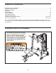
TABLE OF CONTENTS WARNING DECAL PLACEMENT . . . . . . . . . . . . . . . . . . . . . . . . . . . . . . . . . . . . . . . . . . . . . . . . . . . . . . . . . . . . . 2 IMPORTANT PRECAUTIONS . . . . . . . . . . . . . . . . . . . . . . . . . . . . . . . . . . . . . . . . . . . . . . . . . . . . . . . . . . . . . . . . 3 BEFORE YOU BEGIN . . . . . . . . . . . . . . . . . . . . . . . . . . . . . . . . . . . . . . . . . . . . . . . . . . . . . . . . . . . . . . . . . . . . . . 4 ASSEMBLY . . . . . . . . . . . . .
IMPORTANT PRECAUTIONS WARNING: To reduce the risk of serious injury, read the following important precautions before using the weight bench. 1. Read all instructions in this manual before using the weight bench. Use the weight bench only as described in this manual. 12. Make sure that the set screws attaching the Olympic weight adapters are properly tightened each time the adapters are used. 2.
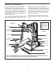
BEFORE YOU BEGIN Thank you for selecting the versatile PROFORM® C840 weight bench. The weight bench offers an impressive array of weight stations designed to develop every major muscle group of the body. Whether your goal is to tone your body, build dramatic muscle size and strength, or improve your cardiovascular system, the weight bench will help you to achieve the specific results you want. reading this manual, call 1-800-4-MY-HOME® (1-800-469-4663).
ASSEMBLY • Place all parts in a cleared area and remove the packing materials. Do not dispose of the packing materials until assembly is completed. Make Things Easier for Yourself This manual is designed to ensure that the weight bench can be assembled successfully by anyone. Most people find that by setting aside plenty of time, assembly will go smoothly.
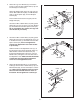
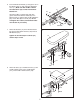
3. Attach the Leg Lever Bracket (5) to the Bench Frame (1) with two M10 x 68mm Bolts (113) and two M10 Nylon Locknuts (97). 3 5 97 Attach the Weight Tube (25) to the Leg Lever (4) with an M8 x 58mm Bolt (106), two M8 Washers (100), a 10mm Spacer (30), and an M8 Nylon Locknut (96). Lubricate 4 Press a 25mm Round Outer Cap (94) onto the Weight Tube (25). 113 96 100 Lubricate an M10 x 68mm Bolt (113) with grease.
6. Insert the Backrest Bracket (7) through the slot in the Bench Frame (1) and under the Adjustment Lever (11). Make sure that the M10 x 62mm Flat Head Screw (27) is under the Backrest Bracket arm. 6 8 97 99 Lubricate an M10 x 155mm Bolt (109) with grease. Attach the Backrest Tubes (8) to the Bench Frame (1) with the Bolt, two M10 Washers (99), and an M10 Nylon Locknut (97). Do not overtighten the Locknut; the Backrest Tubes must be able to pivot easily. 27 1 99 7 7.
9. Slide the Thick Pad Tube (10) into the hole in the Leg Lever Bracket (5). Wet both sides of the Pad Tube with soapy water. Slide two Small Foam Pads (18) onto the Tube as shown. Press two 19mm Square Inner Caps (19) into the Pad Tube. 9 19 18 5 19 Slide a Pad Tube (9) into a hole in the Leg Lever (4). Wet both sides of the Pad Tube with soapy water. Slide two Large Foam Pads (17) onto the Pad Tube as shown. Press two 19mm Square Inner Caps (19) into the Pad Tube. Repeat with the other Pad Tube.
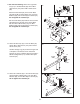
12. See the inset drawing. Attach the Large Base Cap (117) to the Rear Base (33) with an M4 x 16mm Screw (107) and an M8 x 16mm Screw (98). 12 117 33 Attach the Rear Base (33) to the Center Base (32) with two M10 x 78mm Bolts (110), two M10 Washers (99), and two M10 Nylon Locknuts (97). Do not tighten the Locknuts yet. 107 32 Set the Center Base (32) inside of the Foot Plate (48).
15. Attach a Base Cap (47) to the Right Base (34) with an M4 x 16mm Screw (107) and an M10 x 19mm Screw (118). 15 47 113 99 113 Attach the Right Base (34) to the Center Base (32) with three M10 x 68mm Bolts (113), three M10 Washers (99), and two M10 Nylon Locknuts (97). Do not tighten the Locknuts yet. 97 99 118 107 34 32 97 16. Using a rubber mallet, tap the left Rack Foot (46) into the Left Base (35).
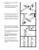
19. Press a Round Joint Bushing (74) into the Left Frame Joint (49). 19 40 Attach the Top Frame (40) to the Left Frame Joint (49) with two M10 x 91mm Bolts (116), four M10 Washers (99), and two M10 Nylon Locknuts (97). Do not tighten the Locknuts yet. 50 99 Assemble the Right Frame Joint (50) to the Top Frame (40) in the same manner. 97 99 116 74 49 20. Attach the Left Frame Joint (49) to the Left Upright (36) with two M10 x 91mm Bolts (116), four M10 Washers (99), and two M10 Nylon Locknuts (97).
23. Slide the Barbell Adapter (59) onto the Weight Bar (55). Thread a 1/4” x 9.5mm Allen Head Set Screw (120) into the Barbell Adapter. Do not tighten the Screw yet. 23 Repeat this step with the other Barbell Adapter (not shown). 55 59 120 24. Attach the Center Upright (37) to the Center Base (32) and Rear Base (33) with an M10 x 78mm Bolt (110), an M10 Washer (99), and an M10 Nylon Locknut (97). Do not tighten the Locknut yet.
25. Insert an M10 x 19mm Hex Head Bolt (132) into the bracket on the Weight Carriage (71) from the side shown. 25 97 70 114 61 Orient the Weight Carriage (71) as shown and slide it onto the Rear Upright (38). 132 Attach the Weight Carriage Stop (70) to the Rear Upright (38), at the indicated hole, with an M10 x 88mm Bolt (114) and an M10 Nylon Locknut (97). Make sure the Square Carriage Bushing (61) is on the bottom. 71 Hole 38 26. Press a 60mm Square Inner Cap (65) into the Rear Top Frame (39).
28. Attach the Butterfly Frame (42) to the Rear Top Frame (39) with two M10 x 78mm Bolts (110), two M10 Washers (99), and two M10 Nylon Locknuts (97). Do not tighten the Locknuts yet. 28 110 99 99 Attach the Butterfly Frame (42) to the Center Upright (37) with two M10 x 68mm Bolts (113), two M10 Washers (99), and two M10 Nylon Locknuts (97). Do not tighten the Locknuts yet. 39 37 97 Tighten all of the M10 Nylon Locknuts (97) used in steps 11–28.
31. Wrap the Butterfly Cable (83) over a “V”-pulley (89). Attach the “V”-pulley and a Large Cable Trap (88) to the Center Upright (37) with an M10 x 60mm Bolt (128) and an M10 Nylon Locknut (97). Make sure the Cable Trap is oriented to hold the Cable in the groove of the “V”-pulley. 31 37 97 89 88 128 83 32. Wrap the Butterfly Cable (83) under a 90mm Pulley (90). Attach the Pulley to the Double “U”bracket (73) with an M10 x 45mm Bolt (112) and an M10 Nylon Locknut (97). 32 83 90 112 97 73 33.
35. Locate the Lat Cable (81). Route the Cable up through the Rear Top Frame (39) and over a 90mm Pulley (90). Attach the Pulley inside the Rear Top Frame with an M10 x 78mm Bolt (110), two M10 Washers (99), two 17mm Spacers (86), and an M10 Nylon Locknut (97). 35 90 39 81 97 99 86 86 99 110 36. Route the Lat Cable (81) over a 90mm Pulley (90) and down through the Rear Top Frame (39).
40. Locate the Low Cable (82). Route the eyelet end of the Cable through the Center Upright (37) and under a 90mm Pulley (90). Attach the Pulley inside the Upright with an M10 x 75mm Bolt (127), two M10 Washers (99), two 17mm Spacers (86), and an M10 Nylon Locknut (97). 40 37 97 99 86 90 86 82 41. Route the Low Cable (82) over a 90mm Pulley (90) as shown. Attach the Pulley to the Double “U”-bracket (73) with an M10 x 45mm Bolt (112) and an M10 Nylon Locknut (97). 99 41 97 112 97 90 82 42.
44. Attach the Low Cable (82) inside the Rear Base (33) with an M10 x 75mm Bolt (127), two M10 Washers (99), two 27mm Spacers (87), and an M10 Nylon Locknut (97). Do not overtighten the Locknut; the Cable must be able to pivot easily. 44 97 99 87 33 82 127 87 99 45. Attach the Butterfly Backrest (80) to the Center Upright (37) with two M6 x 72mm Screws (105) and two M6 Washers (101). 45 80 37 105 101 101 105 46. Make sure that all parts have been properly tightened.
ADJUSTMENTS This section explains how to adjust the weight bench. See the EXERCISE GUIDELINES on page 24 for important information about how to get the most benefit from your exercise program. See the accompanying exercise guide to see the correct form for each exercise. Make sure all parts are properly tightened each time the weight bench is used. Replace any worn parts immediately. The weight bench can be cleaned with a damp cloth and a mild, non-abrasive detergent. Do not use solvents.
USING THE OLYMPIC WEIGHT ADAPTER Press a 48mm Round Inner Cap (23) into the Olympic Adapter (24). Attach the Olympic Adapter to the Weight Tube (25) with a 1/4” x 9.5mm Allen Head Set Screw (120). Make sure that the Set Screw is in the bottom of the Adapter. 25 24 Press a 48mm Round Inner Cap (23) into a Weight Adapter (60). Attach the Weight Adapter to the Curl Bar (76) with a 1/4” x 9.5mm Allen Head Set Screw (120). Make sure that the Set Screw is in the bottom of the Adapter.
ADDING WEIGHTS TO THE BARBELL OR THE WEIGHT CARRIAGE Weight To use the barbell or Weight Carriage (71), slide the desired amount of weight (not included) onto the Barbell Adapters (59) or Weight Carriage. Secure the weights with the Large Weight Clips (77). 59 77 Weight WARNING: Do not place more than 310 pounds on the barbell or 150 pounds on the Weight Carriage (71). Always place the same amount of weight on each side of the barbell or Weight Carriage.
CABLE DIAGRAMS The cable diagrams below show the proper routing of the Lat Cable (81), the Low Cable (82), and the Butterfly Cable (83). Use the diagram to make sure that the cables and the cable traps have been assembled correctly. If the cables have not been correctly routed, the weight bench will not function properly and damage may occur. The numbers show the correct route for each cable. Make sure that the cable traps do not touch or bind the cables. 4 2 Butterfly Cable (83) Length: 1.
TROUBLESHOOTING Make sure all parts are properly tightened each time the weight bench is used. Replace any worn parts immediately. The weight bench can be cleaned using a damp cloth and mild non-abrasive detergent. Do not use solvents. TIGHTENING THE CABLES Woven cable, the type of cable used on the weight bench, can stretch slightly when it is first used. If there is slack in the cables before resistance is felt, the cables should be tightened.
EXERCISE GUIDELINES THE FOUR BASIC TYPES OF WORKOUTS PERSONALIZING YOUR EXERCISE PROGRAM MUSCLE BUILDING To increase the size and strength of your muscles, push them close to their maximum capacity. Your muscles will continually adapt and grow as you progressively increase the intensity of your exercise. You can adjust the intensity level of an individual exercise in two ways: • by changing the amount of resistance used • by changing the number of repetitions or sets performed.
slowly as you stretch and do not bounce. Ease into each stretch gradually and go only as far as you can without strain. Stretching at the end of each workout is an effective way to increase flexibility. Rest for a short period of time after each set. The ideal resting periods are: • Rest for three minutes after each set for a muscle building workout. • Rest for one minute after each set for a toning workout. • Rest for 30 seconds after each set for a weight loss workout.
EXERCISE MONDAY WEIGHT SETS REPS WEIGHT SETS REPS WEIGHT SETS REPS Date: / / AEROBIC EXERCISE TUESDAY Date: / / WEDNESDAY EXERCISE Date: / / THURSDAY AEROBIC EXERCISE Date: / / EXERCISE FRIDAY Date: / / Make photocopies of this page for scheduling and recording your workouts.
EXERCISE MONDAY WEIGHT SETS REPS WEIGHT SETS REPS WEIGHT SETS REPS Date: / / AEROBIC EXERCISE TUESDAY Date: / / WEDNESDAY EXERCISE Date: / / THURSDAY AEROBIC EXERCISE Date: / / EXERCISE FRIDAY Date: / / Make photocopies of this page for scheduling and recording your workouts.
PART IDENTIFICATION CHART See the drawings below to identify small parts used in assembly. The number in parentheses by each drawing is the key number of the part, from the PART LIST in the center of this manual. Important: Some parts may have been pre-assembled for shipping purposes. If a part is not in the parts bag, check to see if it has been pre-attached. If a part is missing, call toll-free 1-877-992-5999. M10 Nylon Locknut (97) M8 x 12mm Shoulder Bolt (131) 1/4" x 9.
M8 x 58mm Bolt (106) M10 x 60mm Bolt (128) M10 x 62mm Flat Head Screw (27) M6 x 63mm Screw (103) M10 x 68mm Bolt (113) M6 x 72mm Screw (105) M10 x 72mm Hex Head Bolt (130) M10 x 75mm Bolt (127) M10 x 78mm Bolt (110) M10 x 88mm Bolt (114) M10 x 91mm Bolt (116) M10 x 92mm Carriage Bolt (111) M10 x 127mm Bolt (126) M10 x 155mm Bolt (109)
PART LIST—Model No. 831.153321 Key Qty. No.
75 68 52 68 96 108 99 97 99 46 131 99 99 99 113 99 113 99 74 91 116 99 41 97 53 68 123 119 91 68 108 99 99 12 116 97 34 66 120 113 99 113 63 69 99 99 50 59 99 79 107 122 99 78 120 58 23 97 118 47 119 67 99 60 57 12 97 26 40 77 55 116 99 76 95 99 56 43 97 22 93 113 22 22 42 60 67 94 93 26 120 119 94 96 92 92 12983 99 97 97 99 97 22 99 23 120 59 97 44 129 96 83 22 95 97 124 63 99 97 97 80 128 113
EXPLODED DRAWING—Model No. 831.
FULL 90-DAY WARRANTY For 90 days from the date of purchase, if failure occurs due to defect in material or workmanship in this WEIGHT BENCH EXERCISER, contact the nearest Sears Service Center throughout the United States and Sears will repair or replace the WEIGHT BENCH EXERCISER, free of charge. This warranty does not apply when the WEIGHT BENCH EXERCISER is used commercially or for rental purposes.