www.proform.com Model No. PFEX71911.1 Serial No. Write the serial number in the space above for reference. Serial Number Decal (under frame) QUESTIONS? If you have questions, or if parts are damaged or missing, DO NOT CONTACT THE STORE; please contact Customer Care. IMPORTANT: Please register this product (see the limited warranty on the back cover of this manual) before contacting Customer Care. CALL TOLL-FREE: 1-888-533-1333 Mon.–Fri. 6 a.m.–6 p.m. MT Sat. 8 a.m.–4 p.m. MT ON THE WEB: www.
TABLE OF CONTENTS WARNING DECAL PLACEMENT . . . . . . . . . . . . . . . . . . . . . . . . . . . . . . . . . . . . . . . . . . . . . . . . . . . . . . . . . . . . . . .2 IMPORTANT PRECAUTIONS. . . . . . . . . . . . . . . . . . . . . . . . . . . . . . . . . . . . . . . . . . . . . . . . . . . . . . . . . . . . . . . . . . 3 BEFORE YOU BEGIN. . . . . . . . . . . . . . . . . . . . . . . . . . . . . . . . . . . . . . . . . . . . . . . . . . . . . . . . . . . . . . . . . . . . . . . .4 PART IDENTIFICATION CHART.
IMPORTANT PRECAUTIONS WARNING: To reduce the risk of serious injury, read all important precautions and instructions in this manual and all warnings on your exercise bike before using your exercise bike. ICON assumes no responsibility for personal injury or property damage sustained by or through the use of this product. 1. Before beginning any exercise program, consult your physician. This is especially important for persons over age 35 or persons with pre-existing health problems. 9.
BEFORE YOU BEGIN Thank you for selecting the new PROFORM® 115 CSX exercise bike. Cycling is an effective exercise for increasing cardiovascular fitness, building endurance, and toning the body. The 115 CSX exercise bike provides an impressive selection of features designed to make your workouts at home more effective and enjoyable. reading this manual, please see the front cover of this manual. To help us assist you, note the product model number and serial number before contacting us.
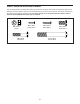
PART IDENTIFICATION CHART Use the drawings below to identify the small parts needed for assembly. The number in parentheses below each drawing is the key number of the part, from the PART LIST near the end of this manual. The number following the key number is the quantity needed for assembly. Note: If a part is not in the hardware kit, check to see if it has been preassembled. Extra parts may be included.
ASSEMBLY • To hire an authorized service technician to assemble this product, call 1-800-445-2480. • In addition to the included tool(s), assembly requires the following tools: • Assembly requires two persons. one Phillips screwdriver • Place all parts in a cleared area and remove the packing materials. Do not dispose of the packing materials until you finish all assembly steps. one adjustable wrench • To identify small parts, see page 5. Assembly may be easier if you have a set of wrenches.
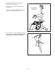
2. Attach the Front Stabilizer (2) to the Frame (1) with two M10 x 75mm Screws (36). 2 2 36 1 3. Orient the Upright (3) and the Top Shield (9) as shown. 3 Have a second person hold the Upright (3) and the Top Shield (9) near the Frame (1) until you complete step 4. Connect the Upper Wire (32) to the Lower Wire (31). Then, pull the excess Upper Wire out of the top of the Upright.
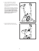
4. Tip: Avoid pinching the wires. Slide the Upright (3) onto the Frame (1). 4 Attach the Upright (3) with four M8 x 18mm Screws (35). Avoid pinching the wires Slide the Top Shield (9) downward and press it onto the Left and Right Shields (17, 18). 3 9 35 35 17 1 18 5. Attach the Seat (12) to the Seat Post (5) with four M8 Locknuts (37). Note: The Locknuts may be preattached to the underside of the Seat.
6. Using an adjustable wrench, tighten the Adjustment Knob (11) into the Frame (1). 6 Next, loosen the Adjustment Knob (11) a few turns, pull it outward, and insert the Seat Post (5) into the Frame (1). Slide the Seat Post (5) upward or downward to the desired position, and release the Adjustment Knob (11) into one of the adjustment holes in the Seat Post. Move the Seat Post upward or downward slightly to make sure that the Adjustment Knob is engaged in one of the adjustment holes in the Seat Post.
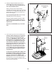
8. Identify the Right Handlebar (48), which is marked with an “R” sticker, and orient it as shown. Make sure that the hexagonal holes are in the indicated location. 8 Avoid pinching the wire 47 While a second person holds the Right Handlebar (48) near the Upright (3), tie the indicated wire tie to the Right Pulse Wire (42). Then, pull the other end of the wire tie upward out of the top of the Upright. 28 Wire Tie 42 Tip: Avoid pinching the wire. Slide the Right Handlebar (48) onto the Upright (3).
10. While a second person holds the Console (6) near the Upright (3), connect the wires on the Console to the Upper Wire (32) and to the Right and Left Pulse Wires (42, 28). 10 Avoid pinching the wire 6 Insert the excess wire downward into the Upright (3) or upward into the Console (6). 32 Tip: Avoid pinching the wires. Attach the Console (6) to the Upright (3) with four M4 x 16mm Screws (40). 11. Attach the Handlebar Cover (19) to the Upright (3) with two M4 x 16mm Screws (40).
. Identify the Right Pedal (26), which is marked with an “R.” Using an adjustable wrench, firmly tighten the Right Pedal clockwise into the right arm of the Crank (13). 12 Tighten the Left Pedal (not shown) counterclockwise into the left arm of the Crank (not shown). Adjust the strap on the Right Pedal (26) to the desired position, and press the end of the strap onto the tab on the Right Pedal. 13 Strap Adjust the strap on the Left Pedal (not shown) in the same way. 26 Tab 13.
HOW TO USE THE EXERCISE BIKE HOW TO ADJUST THE HEIGHT OF THE SEAT HOW TO ADJUST THE PEDAL STRAPS For effective exercise, the seat should be at the proper height. As you pedal, there should be a slight bend in your knees when the pedals are in the lowest position. To adjust the pedal straps, first pull the ends of the straps off the tabs on the pedals. Then, adjust the straps to the desired position, and press the ends of the straps onto the tabs.
CONSOLE DIAGRAM FEATURES OF THE CONSOLE You can even connect your MP3 player or CD player to the console sound system and listen to your favorite music or audio books while you exercise. The advanced console offers an array of features designed to make your workouts more effective and enjoyable. To use the manual mode, see page 15. To use a preset workout, see page 16. To use the sound system, see page 17. To use the user mode, see page 17.
HOW TO USE THE MANUAL MODE 4. Follow your progress with the display. 1. Turn on the console. The left display–This display can show the elapsed time and the approximate number of calories you have burned. The display will change modes every few seconds. Press any button or begin pedaling to turn on the console. When you turn on the console, the display will turn on. A tone will sound and the console will be ready for use.
5. Measure your heart rate if desired. HOW TO USE A PRESET WORKOUT I f there are sheets of plastic on the Contacts metal contacts on the handgrip heart rate monitor, remove the plastic. In addition, make sure that your hands are clean. To measure your heart rate, hold the handgrip heart rate monitor with your palms resting against the metal contacts. Avoid moving your hands or gripping the contacts tightly. 1. Turn on the console. See step 1 on page 15. 2. Select a preset workout.
HOW TO USE THE SOUND SYSTEM During the workout, the workout profile will show your progress (see the drawing on page 16). The flashing segment of the profile represents the current segment of the workout. The height of the flashing segment indicates the resistance level for the current segment.
FCC INFORMATION This equipment has been tested and found to comply with the limits for a Class B digital device, pursuant to part 15 of the FCC Rules. These limits are designed to provide reasonable protection against harmful interference in a residential installation. This equipment generates, uses, and can radiate radio frequency energy and, if not installed and used in accordance with the instructions, may cause harmful interference to radio communications.
MAINTENANCE AND TROUBLESHOOTING Inspect and tighten all parts of the exercise bike regularly. Replace any worn parts immediately. Locate the Reed Switch (21). Turn the Pulley (13) until a Pulley Magnet (16) is aligned with the Reed Switch. Loosen, but do not remove, the indicated M4 x 16mm Screw (40). Slide the Reed Switch slightly closer to or away from the Magnet, and then retighten the Screw. To clean the exercise bike, use a damp cloth and a small amount of mild soap.
HOW TO ADJUST THE DRIVE BELT Remove all the screws from the left and right shields; there are two sizes of screws in the shields—note which size of screw you remove from each hole. Then, gently pull the right shield away from the frame. If the pedals slip while you are pedaling, even while the resistance is adjusted to the highest setting, the drive belt may need to be adjusted. Loosen the M6 x 20mm Hex Screw (46). Then, tighten the M10 x 50mm Hex Screw (33) until the Drive Belt (23) is tight.
EXERCISE GUIDELINES Burning Fat—To burn fat effectively, you must exercise at a low intensity level for a sustained period of time. During the first few minutes of exercise, your body uses carbohydrate calories for energy. Only after the first few minutes of exercise does your body begin to use stored fat calories for energy. If your goal is to burn fat, adjust the intensity of your exercise until your heart rate is near the lowest number in your training zone.
PART LIST Key No. Qty. 1 2 3 4 5 6 7 8 9 10 11 12 13 14 15 16 17 18 19 20 21 22 23 24 25 26 27 28 1 1 1 2 1 1 1 2 1 2 1 1 1 1 2 2 1 1 1 1 1 1 1 1 1 1 1 1 Model No. PFEX71911.1 R0812A Description Key No. Qty.
EXPLODED DRAWING 51 28 12 Model No. PFEX71911.
ORDERING REPLACEMENT PARTS To order replacement parts, please see the front cover of this manual.