Model No. PFEVEX74108.0 Serial No. Write the serial number in the space above for reference. Serial Number Decal QUESTIONS? As a manufacturer, we are committed to providing complete customer satisfaction. If you have questions, or if there are missing parts, please contact us at the numbers or addresses listed below: Call: 08457 089 009 Outside UK: 0 (44) 113 3877133 Fax: 0 (44) 113 3877125 E-mail: csuk@iconeurope.com Write: ICON Health & Fitness, Ltd.
TABLE OF CONTENTS WARNING DECAL PLACEMENT . . . . . . . . . . . . . . . . . . . . . . . . . . . . . . . . . . . . . . . . . . . . . . . . . . . . . . . . . . . . . .2 IMPORTANT PRECAUTIONS . . . . . . . . . . . . . . . . . . . . . . . . . . . . . . . . . . . . . . . . . . . . . . . . . . . . . . . . . . . . . . . .3 BEFORE YOU BEGIN . . . . . . . . . . . . . . . . . . . . . . . . . . . . . . . . . . . . . . . . . . . . . . . . . . . . . . . . . . . . . . . . . . . . . .4 ASSEMBLY . . . . . . . . . . . . .
IMPORTANT PRECAUTIONS WARNING: To reduce the risk of serious injury, read all important precautions and instructions in this manual and all warnings on your exercise cycle before using your exercise cycle. ICON assumes no responsibility for personal injury or property damage sustained by or through the use of this product. 8. Wear appropriate exercise clothes while exercising; do not wear loose clothes that could become caught on your exercise cycle.
BEFORE YOU BEGIN Congratulations for selecting the new PROFORM® 380 ZLX exercise cycle. Cycling is one of the most effective exercises for increasing cardiovascular fitness, building endurance, and toning the entire body. The 380 ZLX exercise cycle offers a selection of features designed to let you enjoy this healthful exercise in the convenience and privacy of your home. after reading this manual, please see the front cover of this manual.
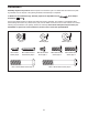
ASSEMBLY Assembly requires two persons. Place all parts of the exercise cycle in a cleared area and remove the packing materials. Do not dispose of the packing materials until assembly is completed. In addition to the included tool(s), assembly requires an adjustable wrench . screwdriver and a Phillips Use the part drawings below to identify the small parts used in assembly. The number in parentheses below each drawing refers to the key number of the part, from the PART LIST near the end of this manual.
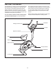
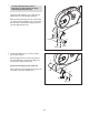
1. 1 To make assembly easier, read the information on page 5 before you begin assembling the exercise cycle. Orient the Rear Stabilizer (14) so that the indicated holes are in the indicated locations. While another person lifts the rear of the Frame (1), attach the Rear Stabilizer (14) to the Frame with two M10 x 54mm Button Screws (33) and two M10 Split Washers (34). Holes 1 34 Holes 33 2. Identify the Right Cap (77), which is marked with a “Right” sticker.
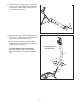
3. While another person lifts the front of the Frame (1), attach the Front Stabilizer (2) to the Frame with two M10 x 78mm Button Screws (67) and two M10 Split Washers (34). 3 2 1 67 34 4. While another person holds the Upright (3) near the Frame (1), connect the Upper Wire Harness (32) to the Lower Wire Harness (31). 4 Gently pull the upper end of the Upper Wire Harness (32) to remove the slack, and slide the Upright (3) onto the Frame (1).
5. While a second person holds the Handlebar (47) near the Upright (3), locate the wire tie in the Upright. 5 See the inset drawing. Tie the lower end of the wire tie to the Pulse Wires (82). Next, pull the other end of the wire tie upward out of the top of the Upright (3). Then, untie and discard the wire tie. Tip: Do not allow the ends of the Pulse Wires to fall into the Upright. Use a piece of tape or an elastic band to hold the Pulse Wires in place until step 7.
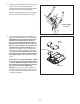
7. Hold the Console Bracket (55) near the Upright (3) as shown, and insert the Upper Wire Harness (32) and the Pulse Wires (82) upward through the hole in the Console Bracket. 7 Attach the Console Bracket (55) to the Upright (3) with two M8 x 25mm Patch Screws (50). 50 55 32 82 3 8. The Console (6) requires four D batteries (not included); alkaline batteries are recommended.
9. While another person holds the Console (6) near the Console Bracket (55), connect the console wire to the Upper Wire Harness (32). Then, connect the console pulse wires to the Pulse Wires (82). 9 Console Wire 6 Insert the excess wires downward into the Upright (3). Tip: Avoid pinching the wires. Attach the Console (6) to the Console Bracket (55) with four M4 x 16mm Screws (40). 32 Console Pulse Wires 55 82 3 10. Orient the Seat Post (5) as shown. Loosen the Seat Post Knob (30) a few turns.
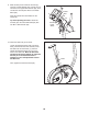
. Orient the Seat (12) and the Seat Carriage (29) as shown. Attach the Seat (12) to the Seat Carriage (29) with four M8 Locknuts (37) and four M8 Split Washers (36). 11 Loosen the Seat Knob (11) and slide the Seat Carriage (29) onto the Seat Post (5) until it stops. Next, attach an M6 x 8mm Patch Screw (56) to the Seat Post (5). Then, adjust the Seat Carriage (29) to the desired position and tighten the Seat Knob (11). 12. Identify the Right Pedal (26), which is marked with an “R.
HOW TO OPERATE THE EXERCISE CYCLE HOW TO ADJUST THE HEIGHT OF THE SEAT For effective exercise, the seat should Seat be at the proper Seat height. As you pedal, Post there should be a Knob slight bend in your Seat knees when the pedPost als are in the lowest position. To adjust the height of the seat, first loosen the seat post knob. Next, pull the knob, slide the seat post upward or downward to the desired position, and then release the knob.
CONSOLE DIAGRAM Resistance Dial FEATURES OF THE CONSOLE In addition, the console offers two heart rate workouts that change the resistance of the pedals to keep your heart rate near a target heart rate while you exercise. The advanced console offers an array of features designed to make your workouts more effective and enjoyable. When you select the manual mode of the console, you can change the resistance of the pedals with a touch of the dial.
4. If the console is operating an exercise cycle, select a unit of measurement. HOW TO ENTER CONSOLE SETTINGS 1. Begin pedaling or press any button on the console to turn on the console. When the console operates an exercise cycle, the console can show speed and distance in either miles or kilometers. A moment after you begin pedaling or press a button, the display will light.
HOW TO USE THE MANUAL MODE The lower left corner of the display will show the distance you have pedaled. 1. Begin pedaling or press any button on the console to turn on the console. Note: If the console is operating an exercise cycle, the distance will be shown in miles or kilometers. If the console is operating an elliptical exerciser, the distance will be shown in total number of revolutions. A moment after you begin pedaling or press a button, the display will light. 2. Select the manual mode.
5. Measure your heart rate if desired. If the display does not show your heart rate, make sure that your hands are positioned as described. Be careful not to move your hands excessively or to squeeze the metal contacts too tightly. For optimal performance, clean the metal contacts using a soft cloth; never use alcohol, abrasives, or chemicals to clean the contacts. If there are sheets of clear Contacts plastic on the metal contacts on the handgrip pulse sensor, remove the plastic.
HOW TO USE A TRAINER WORKOUT 1. Begin pedaling or press any button on the console to turn on the console. A moment after you begin pedaling or press a button, the display will light. 2. Select a trainer workout. To select a trainer workout, press the Profile Workout Select button repeatedly until the number of the desired workout appears in the display. The workout time and a profile of the resistance levels for the workout will also appear in the display.
HOW TO USE A CALORIE GOAL WORKOUT As you exercise, you will be prompted to keep your pedaling pace near the target pace for the current segment. When an upward arrow appears in the display, increase your pace. When a downward arrow appears, decrease your pace. When no arrow appears, maintain your current pace. 1. Begin pedaling or press any button on the console to turn on the console. A moment after you begin pedaling or press a button, the display will light. 2. Select a calorie goal workout.
HOW TO USE A HEART RATE WORKOUT During the workout, the workout profile in the display will show your progress. The flashing segment of the profile represents the current segment of the workout. The height of the flashing segment indicates the target heart rate for the current segment. At the end of each segment of the workout, a series of tones will sound and the next segment of the profile will begin to flash. 1. Begin pedaling or press any button on the console to turn on the console.
MAINTENANCE AND TROUBLESHOOTING HOW TO ADJUST THE BELT Inspect and properly tighten all parts of the exercise cycle regularly. Replace any worn parts immediately. To clean the exercise cycle, use a damp cloth and a small amount of mild soap—never use alcohol, abrasives, or chemicals to clean the exercise cycle. If you can feel the pedals slip while you are pedaling, even when the resistance is at the highest level, the belt may need to be adjusted.
EXERCISE GUIDELINES WARNING: Burning Fat—To burn fat effectively, you must exercise at a low intensity level for a sustained period of time. During the first few minutes of exercise, your body uses carbohydrate calories for energy. Only after the first few minutes of exercise does your body begin to use stored fat calories for energy. If your goal is to burn fat, adjust the intensity of your exercise until your heart rate is near the lowest number in your training zone.
PART LIST—Model No. PFEVEX74108.0 Key No. Qty.
EXPLODED DRAWING—Model No. PFEVEX74108.
ORDERING REPLACEMENT PARTS To order replacement parts, please see the front cover of this manual. To help us assist you, be prepared to provide the following information when contacting us: • the model number and serial number of the product (see the front cover of this manual) • the name of the product (see the front cover of this manual) • the key number and description of the replacement part(s) (see the PART LIST and the EXPLODED DRAWING near the end of this manual) Part No.