OM12001 - Automotive Telematics On-board unit Platform Road Pricing - ECall Rev. 0.75 — 14th August 2012 Preliminary Specification Document information Info Content Title OM12001 - Automotive Telematics On-board unit Platform Short title (1 line) OM12001 (ATOP) Subtitle Road Pricing - ECall Short subtitle (1 line) Telematics Document ID ATOP Preliminary Specification Document type Preliminary Specification Revision number 0.
OM12001 (ATOP) NXP Semiconductors Telematics Revision history Rev Date Description 0.75 9th August 2012 Numerous typos corrected Reference links updated 0.74 6th August 2012 Updated spec for “minus” version, ie. without NFC and security components. Updated label Added IC statement 0.73 1st February 2012 Added RHF indication description to label 0.
OM12001 (ATOP) NXP Semiconductors Telematics 1. Introduction OM12001 (ATOP) is the NXP Semiconductors platform for automotive telematics on-board units (OBU's) for applications such as road pricing and eCall, based upon the following technologies: • • • • • • GSM for communication GPS for localization service NFC for short range communication, e.g.
OM12001 (ATOP) NXP Semiconductors Telematics Virtual Machine for customer application Communication coprocessor with Quad-band GSM/GPRS terminal Localization coprocessor with GPS receiver Near Field Communication (NFC) controller to connect to external vignette, smart card, mobile phone 3 Security processor for providing a source of trust SmartMX smartcard running JCOP 2.4.
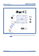
OM12001 (ATOP) NXP Semiconductors Telematics Fig 1. ATOP module connections Figure 2 represents a more conceptual view of OM12001 (ATOP) from a system point of view. ATOP Preliminary Specification Preliminary Specification © NXP B.V. 2012. All rights reserved. Rev. 0.
OM12001 (ATOP) NXP Semiconductors Telematics Application Processor Security Processor Utility Processor Localization Fig 2. NFC GPRS ATOP conceptual view Three main components can be seen in Figure 2: • Application processor: This processor will run code specific to the application (roadtolling, insurance, ...
OM12001 (ATOP) NXP Semiconductors Telematics serial interfaces, the I2S port, ADCs, DAC as well as for memory transfers Serial Interfaces 3 UARTs 2 I2Cs 1 SSP (Synchronous Serial Port) and 1 SPI I2S output/input PWM/Capture unit GPIOs (multiplexed) High speed serial interfaces Ethernet MAC with RMII interface and dedicated DMA controller Full Speed USB 2.
OM12001 (ATOP) NXP Semiconductors Telematics Advanced proprietary multipath algorithms for robust low dropout tracking in very low signals environment SW upgradable 1 Pulse per Second (1PPS) output for synchronization with GPS system clock 4.4 GSM/GPRS coprocessor Connection to mobile networks is provided by a certified communications protocol stack that is field tested worldwide.
OM12001 (ATOP) NXP Semiconductors Telematics OM12001 (ATOP) relies on a SmartMX component with the following features: Common criteria CC EAL5+ certification according to BSI-PP-0002 protection profile Latest built-in security features to avoid power (SPA/DPA), timing, and fault attacks 80 KB EEPROM EEPROM with typical 500000 cycles endurance and minimum 20 years retention time 6144 B RAM 200 KB ROM 75+ KB available for customer applications Secure cryptographic processor High-performanc
OM12001 (ATOP) NXP Semiconductors Telematics 4.8 Battery and Power management Thanks to its integration, OM12001 (ATOP) can be connected directly to a mobile phone battery. All voltage conversion and battery charging management will be handled by OM12001 (ATOP).
OM12001 (ATOP) NXP Semiconductors Telematics Except for a few services provided by NXP to handle communication between the application running on Virtual Machine and virtualized external devices, Utility processor will be completely available to the system integrator. 6.1.1 General features • ARM Cortex-M3 microcontroller, running up to 100 MHz • 512 kB on-chip Flash Program Memory with In-System Programming (ISP) and In-Application Programming (IAP) capabilities.
OM12001 (ATOP) NXP Semiconductors Telematics – One PWM/Timer block with support for three-phase motor control – Real-Time Clock (RTC) with separate power pin; clock source can be the RTC oscillator or the APB clock oscillator – Watchdog Timer.
OM12001 (ATOP) NXP Semiconductors Telematics 6.1.2 Block diagram Fig 3. LPC1768 block diagram ATOP Preliminary Specification Preliminary Specification © NXP B.V. 2012. All rights reserved. Rev. 0.
OM12001 (ATOP) NXP Semiconductors Telematics 6.1.3 Ethernet Ethernet block supports bus clock rates of up to 100 MHz. The Ethernet block contains a full featured 10 Mbit/s or 100 Mbit/s Ethernet MAC designed to provide optimized performance through the use of DMA hardware acceleration. Features include a generous suite of control registers, half or full duplex operation, flow control, control frames, hardware acceleration for transmit retry, receive packet filtering and wake-up on LAN activity.
OM12001 (ATOP) NXP Semiconductors Telematics • Global Acceptance Filter recognizes 11-bit and 29-bit receive identifiers for all CAN buses • Acceptance Filter can provide FullCAN-style automatic reception for selected Standard Identifiers • Full CAN messages can generate interrupts 6.1.6 Power saving modes 6.1.6.
OM12001 (ATOP) NXP Semiconductors Telematics 6.1.6.2 Power modes The LPC1768 support a variety of power control features. There are four special modes of processor power reduction: • • • • Sleep Deep-sleep Power-down Deep power-down The CPU clock rate may also be controlled as needed by changing clock sources, reconfiguring PLL values, and/or altering the CPU clock divider value. This allows a trade-off of power versus processing speed based on application requirements.
OM12001 (ATOP) NXP Semiconductors Telematics Power-down mode: Power-down mode does everything that Deep-sleep mode does, but also turns off the power to the IRC oscillator and the flash memory. This saves more power but requires waiting for resumption of flash operation before execution of code or data access in the flash memory can be accomplished. Deep power-down mode: The Deep power-down mode can only be entered from the RTC block.
OM12001 (ATOP) NXP Semiconductors Telematics • precharge mode: Precharge mode is completely under HW control and will continue until the battery voltage is high enough so that baseband can boot. During precharge, ATOP will provide a 200 mA current. As SW is not yet booted, temperature will not be controlled, i.e. precharge will occur even if battery is outside of advised range for a battery • fast charge: If battery level is higher than 3.1V (i.e.
OM12001 (ATOP) NXP Semiconductors Telematics Fig 6. Charging circuitry Additionally other pins should be connected as follows: • VBAT_SENSE_P must be connected to the battery • VBAT_SENSE_N must be connected to ground • BB_BAT_THERM must be connected to a 10 kOhm pull-down, or to the battery thermistor 7.
OM12001 (ATOP) NXP Semiconductors Telematics 7.3 Current source OM12001 (ATOP) handles internally all its voltage conversion. For Utility Processor, a separate input, VBAT_MC_SNK, is used. Internally, a LDO, controlled by VDD_3V0_SRC_ENA (active high, with internal pull-up), will convert it to the 3V required by the Utility Processor. As described in Figure 7, the output of the LDO is also available externally to power external component, up to a maximum of 100 mA can be drawn.
OM12001 (ATOP) NXP Semiconductors Telematics Fig 8. Internal setup of NFC antennas R1 = 1 K, R2 = 2.7 K, CRX = 1 nF, Cvmid = 100 NF 9. Recommended operating conditions Table 2.
OM12001 (ATOP) NXP Semiconductors Telematics 10. Limiting values Table 3. Symbol Power supply Parameter Min Typ Max Unit Note Vbat_rf Battery voltage for application processor 3.4[1] 4.2 4.8 V Voltage range allowed in case of connection and transmission to GSM network Vbat_no_rf Battery voltage for application processor 3.1 4.2 5.5 V Voltage range allowed without connection to GMS network (i.e. airplane mode) Vbat_mc Battery voltage for utility processor 3.1 4.2 5.
OM12001 (ATOP) NXP Semiconductors Telematics Table 5. Limiting values for micro-controller pins Symbol Parameter Conditions VIAmc Analog input voltage on ADC related pins VImc Input voltage 5V tolerant I/O Min pins[1][2][3] other I/O pins[2] Typ Max Unit -0.5 5.1 V -0.5 5.5 V -0.5 3.6 V Vimc_xtal1 Input voltage for XTAL1 Internal oscillator input 0 - 1.8 V Vomc_xtal2 Output voltage Internal oscillator output 0 - 1.8 V Max Unit 3.2 V [1] 5V tolerant pins, i.e.
OM12001 (ATOP) NXP Semiconductors Telematics 11. Characteristics 12. Static characteristics 12.1 Pins Table 10. Characteristics for micro-controller pins Symbol Parameter VOmc Output voltage Conditions Min 0 VIHmc High level input voltage 2.0 VILmc Low level input voltage Typ Max Unit 3.0 V V 0.8 V IILmc Low level input current VI=0 V; no pull-up 3 µA IIHmc High level input current VI=3.
OM12001 (ATOP) NXP Semiconductors Telematics Table 12. Characteristic for GPS digital interface namely JTAG and GPS_UART2_RXD Symbol Parameter Conditions VIHbb High level input voltage VILbb Low level input voltage IIHbb High level input current IILbb Min Typ Max Unit 0.7 V -10 +10 µA Low level input current -10 +10 µA VOHbb High level output voltage 1.
OM12001 (ATOP) NXP Semiconductors Telematics Table 16. Vperm_ref voltage reference To be used as a reference to connect to BB_* functional pins Symbol Vperm_ref Parameter Min Typ Max Unit Note Output voltage 2.82[1] 3.0[2] 3.18[3] V Follows VBAT_SNK if <3V [1] For VBAT_SNK = 3.1V [2] For VBAT_SNK = 3.6V [3] For VBAT_SNK = 5.5V Table 17. Vadc_ref voltage reference used as power supply reference for internal ADCs Symbol Parameter Min Typ Max Unit Note Vadc_ref Output voltage 2.
OM12001 (ATOP) NXP Semiconductors Telematics 13. Dynamic characteristics 13.1 Power consumption All measured current consumption have been measured at 25°C with a power supply at 3.7V Table 21.
OM12001 (ATOP) NXP Semiconductors Telematics [4] BS_PA_MFRMS = 2, i.e. paging from network will be checked every 470 ms [5] PCL = 19, i.e. 4.9db amplification for GSM900 [6] PCL = 7, i.e. 29.2db amplification for GSM900 [7] PCL = 5, i.e. 33.1 db amplification for GSM900 Table 24. Security processor power consumption Symbol Parameter Min Typ Function switched off Function active Max Unit Note 0 µA included in NFC coprocessor 6 mA Table 25.
OM12001 (ATOP) NXP Semiconductors Telematics 14. Thermal characteristics 14.1 Internal heater2 As described in Table 2, OM12001 (ATOP) can operate between -40 and +85°C, except for the NFC and Security processor which are limited to a -25 to +85°C temperature range. To ensure that operating range can be rapidly reached, an internal heater is available to heat-up the device. The internal heater is controlled by internal micro-controller pin P2.5 (active high).
OM12001 (ATOP) NXP Semiconductors Telematics Fig 9. Internal temperature accuracy 14.3 Battery temperature sensor To improve lifetime, it is recommended to avoid charging batteries, outside of the temperature range specified by their manufacturers, typically 0 to 50°C. For Lithium-Ion battery, the charger circuit inside OM12001 (ATOP) will use by default the internal temperature sensor.
OM12001 (ATOP) NXP Semiconductors Telematics It is recommended to use a standard no-clean SAC solder paste for a lead free assembly process. Fig 10. Reflow profile Table 29.
OM12001 (ATOP) NXP Semiconductors Telematics • 0.8 mm for the outer pads The recommendation for the stencil thickness is 150 µm. Fig 11. Stencil design 18. Marking Figure 12 shows label present on the module. 5.G7-G13, H7-H13, J7, J8, J12, J13, K7, K8, K12, K13, L7, L8, L12, L13, M7-M13, N7-N13 ATOP Preliminary Specification Preliminary Specification © NXP B.V. 2012. All rights reserved. Rev. 0.
OM12001 (ATOP) NXP Semiconductors Telematics Fig 12.
OM12001 (ATOP) NXP Semiconductors Telematics 19. Packing information OM12001 (ATOP) modules are packed in trays. Before packing and shipping, trays have been dry baked for 16 hours at 125°C, according to IPC/JEDEC J-Std-033B.1. OM12001 (ATOP) has been tested according to IPC/JEDEC J-STD 020D and is classified as Moisture Sensitivity Level 3 (MSL3). 20. Package outline ATOP presents itself as a 33x33x3.35 mm module. Ball size is 0.8 mm with a 1.6mm pitch.
OM12001 (ATOP) NXP Semiconductors Telematics Fig 13. OM12001 (ATOP) package outline and dimensions ATOP Preliminary Specification Preliminary Specification © NXP B.V. 2012. All rights reserved. Rev. 0.
OM12001 (ATOP) NXP Semiconductors Telematics 21. Support information For support, please contact support.telematics@nxp.com 22. Test information For production and end of line testing the following tools will be provided: • SW tools to interface to module: – parameters setting (e.g. battery settings, ...) – file download – flash update 23. Safety instructions OM12001 (ATOP) is a class A digital device marketed for use in a commercial, industrial or business environment.
OM12001 (ATOP) NXP Semiconductors Telematics SAR according to EN 62209-1 has not been checked and replaced by MPE calculation, hence the antenna(s) used in the final application must be installed to provide a separation distance of at least 20 centimeters from all persons and must not be co-located or operating in conjunction with any other antenna or transmitter. Additionally, for FCC compliance, the system antenna(s) gain must not exceed 2.24 dBi for mobile and fixed or mobile operating configurations.
OM12001 (ATOP) NXP Semiconductors Telematics Intentionally left blank. ATOP Preliminary Specification Preliminary Specification © NXP B.V. 2012. All rights reserved. Rev. 0.
OM12001 (ATOP) NXP Semiconductors Telematics 24. Appendix 25. Abbreviations Table 30.
OM12001 (ATOP) NXP Semiconductors Telematics Table 30. Abbreviations …continued Acronym Description RSA A public-key encryption technology developed by RSA Data Security, Inc.
OM12001 (ATOP) NXP Semiconductors Telematics 28. Legal information 28.1 Definitions Draft — The document is a draft version only. The content is still under internal review and subject to formal approval, which may result in modifications or additions. NXP Semiconductors does not give any representations or warranties as to the accuracy or completeness of information included herein and shall have no liability for the consequences of use of such information.
OM12001 (ATOP) NXP Semiconductors Telematics Non-automotive qualified products — Unless this data sheet expressly states that this specific NXP Semiconductors product is automotive qualified, the product is not suitable for automotive use. It is neither qualified nor tested in accordance with automotive testing or application requirements. NXP Semiconductors accepts no liability for inclusion and/or use of non-automotive qualified products in automotive equipment or applications.