1Mbps Wireless Networking Wireless Ethernet Client NWH2210/NWH2610 Installation Guide Rev. A1 December 2001 WEC National Datacomm Corporation 4F, No. 24-2, Industry East 4th Road, Science Park Hsin-Chu, Taiwan, R.O.C. Technical Support E-mail: techsupt@ndc.com.tw NDC World Wide Web www.ndc.com.
TRADEMARKS NDC and InstantWave are trademarks of National Datacomm Corporation. All other names mentioned in this document are trademarks/registered trademarks of their respective owners. NDC provides this document “as is”, without warranty of any kind, neither expressed nor implied, including, but not limited to, the particular purpose. NDC may make improvements and/or changes in this manual or in the product(s) and/or the program(s) described in this manual at any time.
Table of Contents INTRODUCTION..............................................................................................................1 SYSTEM REQUIREMENTS.................................................................................................. 1 PLACEMENT GUIDELINES................................................................................................. 1 HOW TO USE THIS GUIDE.................................................................................................
List of Figures FIGURE 1. INFRASTRUCTURE NETWORK.......................................................................... 3 FIGURE 2. A D HOC NETWORK........................................................................................... 4 FIGURE 3. REAR PANEL ...................................................................................................... 5 FIGURE 4. FRONT PANEL.................................................................................................... 5 FIGURE 5.
Introduction Congratulations on choosing an InstantWave Wireless Ethernet Client (WEC). This guide gives instructions on installing the WEC and using the configuration program. The InstantWave WEC is part of a family of easy to use high-performance wireless communication products.
• • Avoid placing the WEC (especially the antenna) close to metal objects (e.g. file cabinets, metal cubicles, etc.) Keep WECs as far away as possible from microwave ovens (10 meters min. is advisable) How to Use this Guide The Installation Guide gives complete instructions for installation of the InstantWave Wireless Ethernet Client (WEC). Use the WEC COMFig tool , see page 7, to change the default WEC settings.
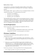
Application Scenarios Infrastructure Network An Infrastructure network is formed by several stations and one or more Access Points (APs), with the stations within a set distance from the AP. Figure 1 depicts a typical Infrastructure network topology. Print Server WEC Computer with Wireless LAN Card Ethernet Ready Computer Access Point Hub Figure 1.
Ad Hoc Network An Ad hoc network is formed by a number of wireless stations (without an Access Point) communicating via radio waves. For the users, the shared resources on the wireless network appear exactly as they would on a regular wired network. The wireless operation of the network is totally transparent. Figure 2 depicts a typical Ad hoc network scenario. Print Server Ethernet Ready Computer WEC Computer with Wireless LAN Card WEC Figure 2.
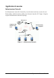
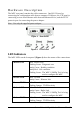
Hardware Description The WEC rear panel contains the cable connectors. One RS-232 port for connecting the configuration cable from a computer COM port, one UTP port for connecting a cross-over Ethernet cable from an Ethernet device, and the DC5V power-in port for connecting the power adapter. Note: Use only the supplied power adapter. Figure 3. Rear Panel Figure 4. Front Panel LED Indicators The WEC LEDs on the front panel (Figure 4) show the status of the connections.
WEC Configuration Tool Installation Before adding a WEC into an existing network, you may need to set basic parameters, e.g. domain name (SSID), security setting (WEP), etc. in order to make it compatible with the existing network. Follow the steps below to connect the WEC to a PC for configuration: step1. Connect the supplied RS-232 cable to the COM port on the WEC and connect the other end to a serial port (COM port) on the PC step2.
Using the WEC COMFig Tool The WEC COMFig Tool is a Windows based utility used to configure the WEC via a COM port connection between the WEC and a PC. It provides the following functions: • Sets WEC parameters (e.g., Network Mode, Domain Name (SSID), Security, etc.) • Diagnoses the WEC hardware and shows the diagnostic results • Upgrades the WEC firmware • Resets the WEC Configuration To start the WEC COMFIG Tool, click Start/Programs/Wec/WEC COMFig Tool.
Password After connecting with the WEC, click on the Password tab to open the Password card (Figure 6). Setting a password prevents unauthorized changes to the WEC configuration settings. The password is blank by default. A password of up to 30 characters may be set. Figure 6. Password Service Click on the Service tab to open the Service card (Figure 7). The Service card provides access to the management features. Figure 7.
Click the View and Modify WEC Configuration button. The Configuration screen will open (Figure 8). General The General card (Figure 8) is the first card in the Configuration section. Figure 8.
Network Mode The WEC allo ws for two types of networking operation, Infrastructure or Ad-hoc. Domain Name (SSID) Identifies the wireless LAN domain that this WEC is in. Only WECs and Access Points with the same SSID can associate with each other. Each SSID may contain up to 31 characters. Empty SSID Click this button to clear the SSID history and reset the SSID to ‘any’. This allows the WEC to associate with the Access Point with the best signal quality, regardless of the SSID setting.
1 and 2Mbps All (1, 2, 5.5, and 11Mbps) Channel Number 802.11b WLAN operates on multiple radio channels. The allowed channels depend on the country you are in. When the WEC is running in Infrastructure mode, the channel number is auto set to the same channel as the Access Point to which it is associated. In Ad hoc mode, the channel must match the channel used by the other wireless stations you wish to communicate with. Select the channel you want to use.
Figure 9. Configuration/Encryption The dropdown Method box lists three options: 1. Disabled (default) - Disables data encryption 2. 40-bit WEP - Enables 40-bit WEP encryption 3. 128-bit WEP - Enables 128-bit WEP encryption Key Generation - There are two ways to generate a security key. The first is by entering any text in the Passphrase field. The passphrase should contain multiple words and may include spaces, numbers, and punctuation characters; the passphrase is case sensitive.
Ethernet This card is used to set the WEC’s Ethernet port settings. Figure 10. Configuration/Ethernet Auto Detect If Auto Detect is selected, the WEC will use the MAC address of the connecting Ethernet device as its MAC address. Fixed Address This option allows you to specify a specific Ethernet device MAC address that is allowed to pass traffic through the WEC.
Perform WEC Self Diagnostic Test On the Service card (Figure 7, page 8), click Perform WEC Self Diagnostic Test. The Hardware Diagnosis screen will open (Figure 11). Figure 11. Hardware Diagnosis Click Start and the tests will commence. As each item is tested, a yellow arrow will appear alongside it. If the test is successful, the arrow will change to a green tick. If a failure occurs, an “X” will appear. You can click Cancel at any time to stop the tests.
Figure 12. Upgrade Firmware Use the Browse button to choose the file to be uploaded to the WEC, or type the file location and name in the File Name field. The Upgrade button will then become enabled. Click Upgrade. The new firmware will be loaded into the WEC’s flash memory area. When the firmware upgrade is complete, click Close to return to the Service card.
Technical Support If you have any problems that you cannot resolve with the information in troubleshooting, or the FAQs at http://www.ndc.com.tw/support/tech/iw_faq.htm please note the following information and contact our technical support team: • • • • • What you were doing when the error occurred What error messages you saw Whether the problem can be reproduced The serial number of the product The firmware version and the debug information NDC Technical Support is available via e-mail: techsupt@ndc.
NDC Limited Warranty Hardware NDC warrants its products to be free of defects in workmanship and materials, under normal use and service, for a period of 12 months from the date of purchase from NDC or its Authorized Reseller, and for the period of time specified in the documentation supplied with each product.
3. Charges: Usually RMA (Returned Material Authorization) items will be returned to the purchaser via airmail, prepaid by NDC. If returned by another carrier, the purchaser will pay the difference. A return freight and handling fee will be charged to the purchaser if NDC determines that there was ‘No Problem Found’ or that the damage was caused by the user. Warning NDC is not responsible for the integrity of any data on storage equipment (hard drives, tape drives, floppy diskettes, etc.).
Specifications General Regulatory Compliance FCC Part 15 Class B. ETS 300 328 and ETS 300 826, CE Mark. ARIB STD-T66 Standards Wireless LAN: IEEE 802.11b, Wi-Fi Compliant Ethernet: IEEE 802.3 Data Rate 11Mbps/5.5Mbps/2 Mbps/1Mbps auto fallback Communication Method Security Half-Duplex LED Indicators Power/Status, Ethernet Link, Ethernet TX/RX, Wireless Link, Wireless TX/RX Interfaces/Connectors 10Base-T: RJ-45 40-bit/128-bit WEP Data Encryption RS-232C: V.24 compliance.
Frequency Stability: Within ± 25ppm Data Modulation Type: BPSK (1Mbps)/QPSK (2/5.5/11Mbps) Data Modulation Speed: 11Mbps/5.
EC DECLARATION OF CONFORMITY The following equipment: Product Name : InstantWave Wireless Ethernet Client Model Number : WEC is hereby confirmed to comply with the requirements set out in the Council Directive on the Approximation of the Laws of the Member States relating to R&TTE Directive(99/ 5/ EC). For the evaluation regarding the electromagnetic compatibility, the following standards were applied.
Appendix This appendix lists the channels supported by the world’s regulatory domains. The channel numbers, channel center frequencies, and regulatory domains are shown in the table.
Index Network Mode ..................................10 Non-overlapping Channels .............11 A Ad Hoc Network.................................4 Always Connect................................13 Auto Detect........................................13 P Basic Rates.........................................10 BSSID.................................................11 Packing List........................................iv Password ..............................................8 Placement Guidelines ..........