The Quick Install Guide for MGate W5x08 Gateway --------------------------------------------------------------------------------------------------------------------------------- www.moxa.com info@moxa.
Connecting the Power The MGate W5X08 series gateway can be powered by connecting a power source to the terminal block, as follows: 1. Loosen or remove the screws on the terminal block. 2. Turn off the power source and then connect a 12–48 VDC power line to the terminal block. 3. Tighten the connections using the screws on the terminal block. 4. Turn on the power source. Note that the unit does not have an on/off switch. It automatically turns on when it receives power.
WLAN Settings The MGate W5X08 supports IEEE 802.11 a/b/g/n wireless function. The wireless function provides more convenient deployment of industrial equipments connecting to network. It has better scalability to meet the requirement of a variety of topologies according to user’s needs of wireless LAN system. Connection Settings The WLAN settings are classified into two types. The first one is “WLAN” setting which includes IP address/Network/Gateway and the method of acquiring IP address.
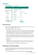
First Time Use Firstly, user can connect with the MGate device and search the unit by using the Device Search Utility. And then configure the MGate through web console. 1. Device Search Utility (called DSU in this instruction) In most situations, users do not know the IP address when setting up a new gateway or configuring an existing gateway. In these cases, users can use an Ethernet cable to connect a host computer and the gateway directly.
The DSU window will appear as shown below. Search the Unit Two methods are available for establishing a connection with MGate: and 錯誤! 找 Search can be used to locate any connected MGate series units in the same network. Use the 錯誤! 找 錯誤! 找不到參照來源。 不到參照來源。. 不到參照來源。 option if you know the IP address of the unit. For example, the default IP of MGate W5X08 series gateway is 192.168.126.254 of the Ethernet interface and 192.168.127.254 of the WiFi interface when user receives a new unit.
To login to the intended device, double-click the device and a web browser will pop-out for detail setting. Type-in the Account name and password to login to the device. The default Account name and Password are “admin” and “moxa”. ATTENTION If 錯誤! 找不到參照來源。 fails to locate the MGate unit, the IP address that you entered might be incorrect. In this case, re-enter the IP address and try searching again.
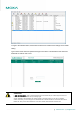
Configuration Once your login to the MGate unit through web console, you will see the overview of this MGate unit including the Model name, Serial No., Ethernet IP Address, WLAN IP Address, etc. Users can click the different configuration functions by the main menu in the left hand side. Protocol Setting The MGate W5X08 gateway has built-in with two serial ports, and users can define the protocol run on each serial port independently.
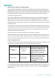
Protocol Settings The sub-clause Protocol Setting function shows the detail of the chosen protocol for each port. The shown web page will be different according to protocol assignment you choose. Example below is with Modbus protocol runs on serial port 1, and DNP3 protocol runs on serial port 2. Modbus setting There are four options can be chosen for Modbus setting: Mode, Slave ID, Priority Control, and Advanced Setting.
Mode Click the currently shown Modbus mode (RTU Master shown in previous figure) for each port for further setting. It includes the mode of the Connected serial device, Response timeout, Inter-character timeout, and Inter-frame delay.
How Slave IDs are Mapped on the MGate W5X08 When a Modbus master requests information from a Modbus slave, the request is addressed to the desired slave's ID, which must be unique on the network. When Modbus networks are integrated by a Modbus gateway, complications can arise if the same slave ID is being used on different networks. If this is not properly addressed, a request sent to that slave ID would receive more than one response, causing communication problems.
Slave ID Map Example Suppose you have two ASCII slave devices on port 1 assigned to slave IDs 3 and 5. The MGate will automatically create a virtual ID range for port 1, which you will need to modify. If slave IDs 3 and 5 are already in use by TCP slaves, the virtual ID range should be set to IDs that are not in use, such as 20 through 22. In that case, you would specify a slave ID offset of -17, since that is the difference between the virtual ID range and the actual slave IDs.
DNP3 Settings There are three fields can be chosen for DNP3 setting: Mode, Address Table, and Advanced Setting. The default DNP3 listen port is 20000, and user can change it to other ports. In general, the MGate passively accepts connections from DNP3 masters or outstations; meanwhile, the MGate also supports actively connections to DNP3 masters or outstations. Mode Parameter Mode Value Outstation, Master Default Outstation Description Role of the DNP3 serial device.
Parameter Remote IP address TCP Port DNP3 address start DNP3 address end DNP3 address offset Advanced Settings Parameter Listen port Value Max 40 characters 1 - 65535 0 – 65519 0 - 65519 -65519 ~ 65519 Value 1 - 65535 Default null 20000 0 0 0 Default 20000 DI/DO The MGate W5X08 is built-in with 1 digital input and 1 digital output. The I/O connection methods are listed as below.
Configuration DI/DO can be monitored and controlled through Modbus command. The related Modbus parameters are listed below. Users can access the DI/DO through Modbus-based utility. Slave ID DI/DO Modbus Address (Base 0) Modbus Address (Base 1) Data Size Function Code DI1 0x0000 0x0001 1 bit 01: Read coils DO1 0x0010 0x0011 1 bit 255 05: Write single coil 15: Write multiple coils We use Modbus Poll shareware for demonstration. Related settings.
DO Users can change the slave ID or check the status of current DI/DO values via web console. Note that the latest version of MGate W5X08 will built-in with 2 DI and 2 DO. --------------------------------------------------------------------------------------------------------------------------------- www.moxa.com info@moxa.
LED Indicator Type Color Green PWR1/PWR2 Off Green Ready Ethernet Link WLAN Red Off Green Amber Off Green RF (signal strength) Green P1/P2 (Serial signal) Green Amber Off Meaning Power is being supplied to power input PWR1, PWR2. Power is off, or power error condition exists. Steady On: Power is on and the gateway is functioning normally. Blinking: The gateway has been located by MGate Manager’s Location function. Steady On: Power is on and gateway is booting up.
Appendix --------------------------------------------------------------------------------------------------------------------------------- www.moxa.com info@moxa.
D. Federal Communication Commission Interference Statement This equipment has been tested and found to comply with the limits for a Class B digital device, pursuant to Part 15 of the FCC Rules. These limits are designed to provide reasonable protection against harmful interference in a residential installation. This equipment generates, uses and can radiate radio frequency energy and, if not installed and used in accordance with the instructions, may cause harmful interference to radio communications.