D Funktionsbeschreibung/ Montageanweisung Steuermodul DSM 400 G Operation/ Installation Control module DSM 400 M.-Nr.
Inhalt/Contents Funktionsbeschreibung. . . . . . . . . . . . . . . . . . . . . . . . . . . . . . . . . . . . . . . . . 3 Montage Wand-Dunstabzugshaube . . . . . . . . . . . . . . . . . . . . . . . . . . . . . . . . . . . . . . . . . . . . 5 Insel-Dunstabzugshaube. . . . . . . . . . . . . . . . . . . . . . . . . . . . . . . . . . . . . . . . . . . . . 7 Elektrischer Anschluss Fensterkontaktschalter . . . . . . . . . . . . . . . . . . . . . . . . . . . . . . . . . . . . . . . . . . . . . .
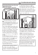
Funktionsbeschreibung Gleichzeitiger Betrieb einer Dunstabzugshaube und einer raumluftabhängigen Feuerstätte Bei gleichzeitiger Nutzung der Dunstabzugshaube und einer raumluftabhängigen Feuerstätte im gleichen Raum oder Lüftungsverbund ist größte Vorsicht geboten. Raumluftabhängige Feuerstätten sind z.B.
Funktionsbeschreibung Das Steuermodul bietet folgende Möglichkeiten: 1. Anschluss eines Fensterkontaktschalters Kann die nötige Zuluftversorgung nur über ein geöffnetes Fenster sichergetellt werden, bietet das Steuermodul die Möglichkeit, einen Fensterkontaktschalter anzuschließen. Er ermöglicht, dass die Dunstabzugshaube nur bei ausreichend geöffnetem Fenster betrieben werden kann.
Montage Wand-Dunstabzugshaube ^ Die Befestigungsschrauben des Kamins herausdrehen und den Kamin lösen. Dazu dient der Hebel, der der Dunstabzugshaube beiliegt. ^ Das Teleskop aus den Wandschienen ziehen und abnehmen. ^ Die Dunstabzugshaube vom Stromnetz trennen. ^ Den Kamin abnehmen.
Montage ^ Die externen Komponenten anschließen (siehe Kapitel "Elektrischer Anschluss" und "Schaltplan"). Die jeweiligen Abdeckungen der Anschlussklemmen lassen sich mit einem Schraubendreher herausbrechen. ^ Das Steuermodul mit den beiliegenden Schrauben seitlich an die Elektronikeinheit der Dunstabzugshaube schrauben. ^ Das Anschlusskabel in die Buchse auf der Elektronikeinheit stecken. ^ Das Kabel verlegen und in die vorgesehenen Halterungen stecken.
Montage Insel-Dunstabzugshaube ^ Die Dunstabzugshaube vom Elektronetz trennen, dazu – die Sicherung der Hausinstallation ausschalten oder – die Schraubsicherung der Hausinstallation ganz herausschrauben. ^ Das Steuermodul in den Schacht einschieben und mit den beiliegenden Schrauben befestigen. ^ Den Abdeckrahmen nach unten abziehen. ^ Das Anschlusskabel des Steuermoduls in die rechte Buchse an der Dunstabzugshaube stecken.
Elektrischer Anschluss Fensterkontaktschalter An den rechten Anschluss a des Steuermoduls lässt sich ein Fensterkontaktschalter anschließen. Bei geschlossenem Fenster (Fensterkontaktschalter geöffnet) lässt sich das Gebläse nicht einschalten. Die Kontrollleuchte der Ein/Aus-Taste der Dunstabzugshaube blinkt. Das Gebläse der Dunstabzugshaube lässt sich nur einschalten, wenn das Fenster geöffnet ist (Fensterkontaktschalter ist geschlossen) und ausreichend Zuluft nachströmen kann.
Elektrischer Anschluss Zusatzlichttaster (Anschluss nur durch eine Elektro-Fachkraft) Am mittleren Anschluss b des Steuermoduls lässt sich ein in der Gebäudeinstallation integrierter Lichttaster anschließen. Damit kann die Beleuchtung der Dunstabzugshaube ein- und ausgeschaltet bzw. gedimmt werden (abhängig von der Geräteausstattung). Falls kein Fensterkontaktschalter angeschlossen wird, muss der rechte Anschluss gebrückt werden. Die Beleuchtung lässt sich weiterhin auch an der Dunstabzugshaube schalten.
Elektrischer Anschluss Potentialfreier Kontakt. (Anschluss nur durch eine Elektro-Fachkraft) Der linke Anschluss c des Steuermoduls bietet einen potentialfreien Kontakt. Er kann z.B. dazu genutzt werden, externe Geräte in Abhängigkeit vom Schaltzustand des Gebläses der Dunstabzugshaube zu steuern. Falls kein Fensterkontaktschalter angeschlossen wird, muss der rechte Anschluss gebrückt werden. Der Kontakt liefert keine definierte Spannung (potentialfrei). Damit ist er universell einsetzbar.
Operation Using a cooker hood at the same time as another heating appliance that depends on the air from the room In order to ensure safe operation, and to prevent gases given off by the heating appliances from being drawn back into the room when the extractor and the heater are in operation simultaneously, an underpressure in the room of 0.04 mbar (4 pa) is the maximum permissible.
Operation The control module enables the following: 2. Potential free connection 1. Connection to a window contact switch This enables an external appliance to be controlled according to the switch setting on the cooker hood fan. If adequate ventilation to the room can only be ensured by having a window open, then the control module can be used to connect a window contact switch to the appliance. Once connected the cooker hood can only be operated when the window is sufficiently open.
Installation Wall-mounted cooker hood ^ Unscrew the fixing screws on the tower and loosen the tower. Use the lever supplied with the cooker hood to help you. ^ Pull the telescopic extension piece off the wall retainers and take it off. ^ Disconnect the cooker hood from the mains electricity supply. ^ Take the tower off.
Installation ^ Connect all external components (see "Electrical connection" and "Wiring diagram"). The covers over the supply terminals can be removed using a screwdriver. ^ Using the screws supplied secure the control module to the electronic unit at the side of the cooker hood. ^ Plug the connection cable into the socket on the electronic unit. ^ Arrange the cable as shown and clip it into the cable clips provided.
Installation Island-mounted cooker hood ^ Disconnect the cooker hood from the mains supply by - switching it off at the wall socket and removing the plug; or - withdrawing the fuse from the fused spur connection unit; or - withdrawing the mains fuse; or removing the screw-out fuse (in countries where this is applicable). Ensure current is not supplied to the appliance while maintenance or repair work is being carried out. ^ Pull the cover plate downwards.
Electrical connection Window contact switch The window contact switch connects to the right hand terminal a on the control module. When the window is closed (window contact switch open) the cooker hood fan cannot be switched on. The On/Off button indicator light on the cooker hood will flash. The cooker hood fan can only be switched on when the window is open (window contact switch closed) and sufficient air can be drawn into the room. The same applies to operation with an external fan motor.
Electrical connection Additonal light switch (connection must be made a suitably qualified electrician only) Connection can be made to a light switch in the home via the middle terminal b in the control module. This will then enable the cooker hood lighting to be switched on and off, or dimmed (depending on model). If a window contact switch has not been connected to the control module, then the right hand terminal must be bridged.
Electrical connection Potential free contact. (connection must be made a suitably qualified electrician only) Potential free contact can be made using the left-hand terminal c on the control module. This enables an external appliance to be controlled according to the switch setting on the cooker hood fan. If a window contact switch has not been connected to the control module, then the right hand terminal must be bridged.
Schaltplan Wand-Dunstabzugshaube Wiring diagram Wall-mounted cooker hood 19
Schaltplan Wiring diagram Insel-Dunstabzugshaube 20 Island-mounted cooker hood
Änderungen vorbehalten / 4607 M.-Nr.