Installation instructions Steam oven DG 4064 / DG 4164 DG 4064 L / DG 4164 L To avoid the risk of accidents or damage to the appliance it is essential to read these instructions before it is installed and used for the first time. en - GB M.-Nr.
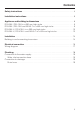
Contents Safety instructions. . . . . . . . . . . . . . . . . . . . . . . . . . . . . . . . . . . . . . . . . . . . . . . . . 4 Installation instructions . . . . . . . . . . . . . . . . . . . . . . . . . . . . . . . . . . . . . . . . . . . . 5 Appliance and building-in dimensions . . . . . . . . . . . . . . . . . . . . . . . . . . . . . . . . 6 DG 4064 / DG 4164 in a 380 mm high niche. . . . . . . . . . . . . . . . . . . . . . . . . . . . . . 6 DG 4064 / DG 4164 and AB 45-7 in a 450 mm high niche . . . . .
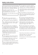
Safety instructions The water inlet hose must be flushed through before using the appliance for the first time, and after any work has been carried out to the plumbing system. This is to remove any deposits which may have collected in the inlet hose and at the stopcock. ~ This steam oven must only be installed in a suitable tall housing unit. ~ The appliance must be installed at such a height that small children cannot reach the appliance door, which gets hot during use.
Installation instructions Plumbing Installation height ^ A cut-out a, as illustrated below, is required in the tall housing unit for feeding the water inlet and outlet hoses through. This is to ensure that there is adequate space for any movement in the hoses during operation and thus prevent the risk of damage to the hoses and any subsequent water damage. The distance from the floor to the middle of the appliance must not exceed 1600 mm. b Isolator switch position.
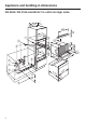
Appliance and building-in dimensions DG 4064 / DG 4164 in a 380 mm high niche 45 2 200 cm 0 55 a -568 560 527 22 55 h c d e 68 -5 560 378 05 593-595 fg 500 5 59 2 5 4 6 270 54 54 i 385 55 b 380 5 59 22
Appliance and building-in dimensions a Cut-out in the housing unit for feeding the water inlet and outlet hoses through b Isolator switch position. Important UK: Do not position the isolator behind the appliance! c Stopcock (cold water connection) d Water inlet connection with safety valve e Water inlet connection hose f Second separate siphon g Do not connect the drain hose here! h Drain hose Important: The top end of the drain hose i must not be higher than 500 mm where it connects to the odour trap.
Appliance and building-in dimensions DG 4064 / DG 4164 and AB 45-7 in a 450 mm high niche 2 45 200 cm 65 595 0 55 a -568 560 527 22 55 h c d e 8 56 60- 378 05 593-595 fg 500 5 59 2 5 5 4 8 270 54 54 i 385 55 b 448-452 5 59 22
Appliance and building-in dimensions a Cut-out in the housing unit for feeding the water inlet and outlet hoses through b Isolator switch position. Important UK: Do not position the isolator behind the appliance! c Stopcock (cold water connection) d Water inlet connection with safety valve e Water inlet connection hose f Second separate siphon g Do not connect the drain hose here! h Drain hose Important: The top end of the drain hose i must not be higher than 500 mm where it connects to the odour trap.
Appliance and building-in dimensions DG 4064 L / DG 4164 L in a 380 mm high niche 200 cm 2 45 95 55 h 68 0-5 378 05 593-595 fg c d e 1 56 500 5 22 5 4 10 700 270 54 54 i 63 324 560 552 55 -568 385 b a 380 0 55 5 59 22 59
Appliance and building-in dimensions a Cut-out in the housing unit for feeding the water inlet and outlet hoses through b Isolator switch position. Important UK: Do not position the isolator behind the appliance! c Stopcock (cold water connection) d Water inlet connection with safety valve e Water inlet connection hose f Second separate siphon g Do not connect the drain hose here! h Drain hose Important: The top end of the drain hose i must not be higher than 500 mm where it connects to the odour trap.
Appliance and building-in dimensions DG 4064 L / DG 4164 L and AB 45-7 in a 450 mm high niche 45 2 200 cm 65 595 05 95 55 8 h c d e 56 60- 378 05 593-595 fg 1 500 5 22 5 59 5 4 12 700 270 54 54 i 324 56 63 552 55 8 0-56 385 b a 448-452 55 59 22
Appliance and building-in dimensions a Cut-out in the housing unit for feeding the water inlet and outlet hoses through b Isolator switch position. Important UK: Do not position the isolator behind the appliance! c Stopcock (cold water connection) d Water inlet connection with safety valve e Water inlet connection hose f Second separate siphon g Do not connect the drain hose here! h Drain hose Important: The top end of the drain hose i must not be higher than 500 mm where it connects to the odour trap.
Installation Building in and connecting to services DG 4064 / DG 4164 ^ Before connecting the appliance to the mains supply you must disconnect the electricity supply to the isolator switch. See "Electrical Connection". ^ Connect the power supply cable to the isolator switch and to the mains connection box on the appliance. ^ Feed the water inlet and drainage hoses through the cut-out in the base of the housing unit.
Electrical connection All electrical work should be carried out by a suitably qualified and competent person, in strict accordance with current local and national safety regulations (BS 7671 in the UK). Installation, repairs and other work by unqualified persons could be dangerous. The manufacturer cannot be held liable for unauthorised work. Ensure power is not supplied to the appliance until after installation or repair work has been carried out. The appliance must only be operated when built-in.
Electrical connection WARNING THIS APPLIANCE MUST BE EARTHED The electrical safety of this appliance can only be guaranteed when continuity is complete between it and an effective earthing system, which complies with current local and national safety regulations. It is most important that this basic safety requirement is present and regularly tested and where there is any doubt, the electrical wiring in the home should be inspected by a qualified electrician.
Electrical connection Wiring diagram N.B. This appliance is supplied single phase only in the UK.
Plumbing Connection to the water supply – This appliance must be connected to a mains drinking water supply only. – The steam oven needs to be connected to the mains water supply and to the drainage system by a fully qualified person in accordance with national and local Water Authority regulations. Water inlet connection hose The appliance is supplied as standard with a special 2.5 m long water connection hose with a solenoid valve, flow regulator and 3/4" threaded union. The 2.
Plumbing Connection to drainage A siphon with a fixed hose connection point must be provided in the base unit for the drain hose. Often the only connection point available is on the sink drain outlet. This connection point g must not be used. Water draining through it would be too noisy and odours can occur. A second separate siphon h must be provided which can be connected via a T-connection piece or via a separate drainage point. See "Appliance and building-in dimensions". Drain hose The standard 2.
Alteration rights reserved / 2810 M.-Nr.