
Manual
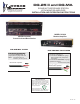


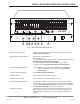

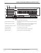
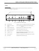

Table Of Contents

PAGE 5 of 28
[24] Mic/Talkback 5-Pin Header Connects to remote station (microphones, audio mixer & speakers)
for each zone.
[25] Relay Output 3-Pin Header Relay output (COM, NC, and NO). Common (COM) and Normally
Open (NO) closes whenever that zone goes into alarm.
[26] Talkback Control 5-Pin Header Connects to the DG-MA for talkback operation.
[27] Power Breaker 6.3A, 28Vdc power circuit breaker.
[28] Audio Out Jack Connects to DG-MA for listening to monitored audio.
[29] Power Header Accepts 15Vdc from power supply (included).
Fig. 2 DG-25 Rear Panel LayoutIII
24
25
26
27
28
29
ZONE 22 ZONE 18 ZONE 15 ZONE 12 ZONE 9 ZONE 5
ZONE 6 ZONE 2
ZONE 1
ZONE 3
ZONE 4ZONE 8
ZONE 7ZONE 11ZONE 14ZONE 17
ZONE 16 ZONE 13 ZONE 10
TO RESET
ZONE 24
ZONE 25
ZONE 23 ZONE 19
ZONE 20
PUSH IN
&
RELEASE
AUDIO OUT
1 2 3 4 5
TB GND
TB RETURN
TB AUDIO
ALL CALL CTRL
GND
ZONE 21
JP51
15VDC. 8A
+15VDC GND
LOUROE ELECTRONICS 6955 VALJEAN AVENUE, VAN NUYS, CA 91406 TEL (818) 994-6498 FAX 994-6458
Website: www.louroe.com Email: sales@louroe.com
(818)
INSTALLATION AND OPERATING INSTRUCTIONS
DG-25III 2/08