LOUROE E LECTRONIC S 6955 VALJEAN AVE, VAN NUYS, CA 91406 PH: (818)994-6498 / FAX: (818)994-6458 sales@louroe.com / www.louroe.
DG-25III 2/08
INSTALLATION AND OPERATING INSTRUCTIONS TABLE OF CONTENTS: Page 1 DG-25III QUICK REFERENCE Page 1 DG-25III APPLICATION Page 2 DESCRIPTION OF PARTS (FRONT PANEL LAYOUT) Page 5 DG-25III REAR PANEL LAYOUT Page 6 DG-MA DESCRIPTION (FRONT PANEL LAYOUT) Page 7 DG-MA REAR PANEL LAYOUT Page 8 OPERATIONS Page 9 INSTALLATION Page 10 MICROPHONE CONNECTIONS (CONNECTIONS TO MODEL TLI) Page 11 CONNECTION TO TLMC Page 12 CONNECTIONS TO PLUG-IN CONNECTOR (AUDIO AND RELAY) Page 13 DG-25III AND DG-MA
INSTALLATION AND OPERATING INSTRUCTIONS QUICK REFERENCE: Wiring Requirements: If using microphones for one-way / listen-only: 2 Conductor shielded cable, 22-gauge with a 24-gauge drain wire. West Penn 452 or equivalent If using speaker/microphones for two-way listen/talkback: 4 Conductor (with the same jacket): Microphone Connection: 2 Conductor shielded, 20-gauge with a 22-gauge drain wire.
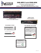
INSTALLATION AND OPERATING INSTRUCTIONS DESCRIPTION: The DG-25III Audio Alarm Base Station is of panel construction and mounts in a standard 19” equipment rack. All controls and indicators are mounted on the front panel and all electrical connections are made at the rear of the unit. DC power is supplied to the DG-25III by an external power supply unit (included) which connects to 120 VAC.
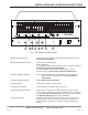
INSTALLATION AND OPERATING INSTRUCTIONS ZONES POWER MONITOR TALKBACK AUTO-RESET TIME DELAY THRESHOLD SENSITIVITY SENSITIVITY OFF ON NON-ALARM MONITOR RESET ON/AUDIO ALERT DG-25III LOUROE E L E C TR O N IC S ALARM LEVEL SET-UP CONTROLS ALARM INPUT ALARM DELAY INPUT 8 TRIGGER 9 10 TIME RESET 11 12 ALARM DELAY POWER 13 14 15 Fig. 1 DG-25III Front Panel Layout [8] Alarm Delay Input Jack Used for testing the length of alarm delay settings as shown by the Alarm Delay Indicator[18].
INSTALLATION AND OPERATING INSTRUCTIONS ZONES POWER MONITOR TALKBACK OFF AUTO-RESET TIME DELAY THRESHOLD SENSITIVITY SENSITIVITY RESET ON NON-ALARM MONITOR ON/AUDIO ALERT DG-25III LOUROE E L E C TR O N IC S ALARM LEVEL SET-UP CONTROLS ALARM INPUT ALARM DELAY INPUT TRIGGER TIME RESET ALARM DELAY POWER 16 17 18 19 Fig. 1 DG-25III Front Panel Layout 20 21 [16] Keyswitch Turns ON power to the unit. Also turns ON the Sonalert Buzzer [4].
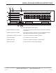
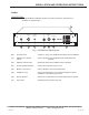
INSTALLATION AND OPERATING INSTRUCTIONS 25 ZONE 19 ZONE 24 TB GND ZONE 23 TB RETURN ZONE 18 GND ZONE 22 ALL CALL CTRL 26 TB AUDIO 24 1 2 3 4 5 JP51 ZONE 20 ZONE 15 ZONE 12 ZONE 9 ZONE 5 ZONE 1 ZONE 16 ZONE 13 ZONE 10 ZONE 6 ZONE 2 ZONE 17 ZONE 14 ZONE 11 ZONE 7 ZONE 3 ZONE 8 ZONE 4 AUDIO OUT ZONE 25 ZONE 21 TO RESET PUSH IN & RELEASE 27 15VDC. 8A +15VDC GND 28 29 Fig.
INSTALLATION AND OPERATING INSTRUCTIONS DG-MA DESCRIPTION: The DG-MA Monitor/ Talkback Amplifier is of panel construction and mounts in a standard 19” equipment rack. 37 MIC TALKBACK LEVEL TALKBACK INDICATOR ALL CALL MONITOR LEVEL POWER HEADPHONES DG-MA 30 31 32 33 34 35 36 Fig. 3 DG-MA Front Panel Layout [30] AUX. MIC Jack Accepts ¼ “ plug from a handheld microphone used for talkback.
INSTALLATION AND OPERATING INSTRUCTIONS 38 43 INPUT AUDIO OUTPUT 1 39 2 3 4 40 5 41 42 Fig. 4 DG-MA Rear Panel Layout [38] Audio Input Jack Accepts audio playback from a DVR, VCR, etc. [39] Audio Output Jack Provides audio for recording to a DVR, VCR, etc. [40] Control Terminal Block Connects to the DG-25III base station and provides talkback control and audio to the DG-25III. [41] DG-25III Input Jack Accepts monitored audio from DG-25III.
INSTALLATION AND OPERATING INSTRUCTIONS OPERATION: The DG-25III Audio Alarm Base Station is normally paired with the DG-MA Monitor/Talkback Amplifier for utilizing the monitor and talk back capabilities of the unit. The operation below includes the DG-MA unit. The Keyswitch[16] has three functions. At position 1, it turns “OFF” the power to the DG-25III. At position 2, it turns “ON” power as indicated by the Power Indicator LED[3].
INSTALLATION AND OPERATING INSTRUCTIONS OPERATION (cont.): Talkback to a given zone is accomplished by plugging the provided handheld microphone into the AUX Mic Jack[30] on the DG-MA front panel and holding down the respective Zone Selector Switch[1]. To talk to all zones at once, press the All Call Pushbutton Switch[33]. The volume of the talkback audio heard at the zone is set by the Talkback Level Control [31] on the front of the DG-MA.
INSTALLATION AND OPERATING INSTRUCTIONS INSTALLATION-Electrical: All electrical installations are made at the rear of the unit. MICROPHONE CONNECTIONS: Connect WEST PENN 356 (sample cable used) to remote station such as a Louroe TLI as shown in Fig. 3 below. Connect the 3 wires wrapped with a shield to microphone terminals marked “A”, “B”, and “C”. Red to “A”, black to “B” and bare or drain wire to “C”. Connect the other two unshielded cables to speaker 70V transformer .
INSTALLATION AND OPERATING INSTRUCTIONS Rear of TLMC SP 6 7 Speaker Positive Speaker Return Wire A Time Selector Dip Switch B C MIC +12VDC Supply MIC Audio Ground Normal or Timed Audio Selector Switch 600 Ohm / 70 Volt Selector Switch Factory Set at 70V Speaker Level Control Factory Set Do Not Adjust 4 Conductor Cable West Penn 356 or Equivalent To Base Station Call Button Fig.
INSTALLATION AND OPERATING INSTRUCTIONS CONNECTIONS TO PLUG-IN CONNECTOR (AUDIO): Prior to connecting the microphone cables to the DG-25III plug-in connectors, each microphones should be checked for proper operation. This can be done quickly by connecting the Louroe PTA (portable test amplifier) to each microphone cable. The battery powered PTA powers the microphone under test and monitors its output though the installed cabling. This eliminates any faulty microphone circuits before final testing.
INSTALLATION AND OPERATING INSTRUCTIONS DG-25III AND DG-MA CONNECTIONS ZONE 19 TB AUDIO TB GND ZONE 15 TB RETURN GND ZONE 18 ALL CALL CTRL Connect the DG-25III to the DG-MA as shown in Fig 8. Both control blocks of the DG25III and DG-MA are marked “1,2,3,4,5”. Connect terminal “1” of DG-25III to terminal “1” of DG-MA.
INSTALLATION AND OPERATING INSTRUCTIONS CONNECTION TO A DVR, VCR OR OTHER RECORDING DEVICE: Remove the jumper (fig 9A) that connects the Audio Input Jack[38] to the Audio Output Jack [39] located at the rear of the DG-MA. Using a dual RCA cable, connect the Audio Input Jack[38] of the DG-MA to the Audio Output Jack of the recorder. Connect the Audio Output Jack[39] of the DG-MA to the Audio Input Jack of the recorder. See Fig. 9 below.
INSTALLATION AND OPERATING INSTRUCTIONS CONNECTION TO AN AUDIO MIXER/COMBINER: Up to six microphones or four speakers can be installed in one zone by using Louroe MLA-6 audio mixer;/combiner unit. See Fig. 10 for connecting speaker/microphone combination units and Fig. 11 for microphone only unit. Fig. 10 shows connection for only one speaker/microphone unit. Additionally, up to 6 microphones and 4 speakers can be installed to this unit by connecting the microphone cables to inputs “MIC 2” through “MIC 6”.
INSTALLATION AND OPERATING INSTRUCTIONS CONNECTION TO AN AUDIO MIXER/COMBINER (cont.): Fig. 11 shows connection for two microphones. Additional microphones are connected the same way as shown for “MIC 1” and “MIC 2”. MLA - 6 (Audio Mixer / Combiner) Red Black Bare Red Black Bare West Penn 452 To Base Station West Penn 452 Mic 1 Mic 2 Fig.
INSTALLATION AND OPERATING INSTRUCTIONS POWER CONNECTIONS: Plug the DG-25III power supply unit to the 3-pin right angle closed Power Header[29] marked “15 Vdc” located at the rear of the DG-25III unit. Push firmly and make sure that the locking tables hold the plug-in connector in place. Plug the power supply to a 110 Vac outlet. Plug the DG-MA AC cord to a 110 Vac outlet. PUSH IN & RELEASE Black Green White to power source Fig.
INSTALLATION AND OPERATING INSTRUCTIONS PARALLELING TWO DG-25III’s: ZONE 18 ZONE 15 ZONE 19 ZONE 16 ZONE 20 ZONE 17 ZONE 21 Two DG-25III units can be paralleled so that a zone can be monitored and controlled from two different locations. See fig. 14 for interconnection diagram between two DG-25III’s and DG-MA. See Fig. 15 for interconnecting the two plug-in connectors of two DG-25III’s. Note that only one DG-25III gives power to the remote microphone as shown by two end cables not connected.
INSTALLATION AND OPERATING INSTRUCTIONS CONNECTING AN EXTERNAL AMPLIFIER: An external amplifier can be connected between the DG-MA and DG-25III to boost the power of its talkback capability. The DG-MA is factory set with a 70V audio output. Before connecting to an external amplifier, change the audio output to 600 Ohms as follows. Remove the top lid or cover of the DG-MA is a slide switch located near the large black capacitor and with the number 230 visible.
INSTALLATION AND OPERATING INSTRUCTIONS OPERATION AND TEST: 1). Apply power to the DG-25III and DG-MA. Turn “ON” the switch of the DG-25III power supply unit. Using the Keyswitch[16], turn “ON” power to the DG-25III by rotating clockwise to “ON” position. The Power Indicator LED[3] located on the top right hand corner of the front panel will light. Turn “ON” power to ther DG-25III Tester by pushing the Tester Power Switch[13]. The Audio Level Indicator[17] and Alarm Delay Indicator[18] will light.
INSTALLATION AND OPERATING INSTRUCTIONS 7 21 22 INCREASE INCREASE DECREASE DECREASE 6 Fig. 16 Setting the audio threshold sensitivity OPERATION AND TEST (cont.): 12). Set the audio threshold as follows: a. Connect the cable with a 3.5mm mono plug on both ends (supplied) between the Audio Alarm Input Jack[6] and Audio Alarm Output Jack[22]. See Fig. 16. b.
INSTALLATION AND OPERATING INSTRUCTIONS 57 19 INCREASE 23 DECREASE INCREASE INCREASE DECREASE DECREASE 5 8 Fig. 17 Setting the alarm time delay OPERATION AND TEST (cont.): 13). Set the alarm time delay as follow: a. Connect the second test cable with a 3.5mm stereo plug on one end and a 3-pin din plug on the other (supplied) between the Alarm Delay Output Jack[23] and the Alarm Delay Input Jack[8]. See Fig. 17 above. Plug the 3.
INSTALLATION AND OPERATING INSTRUCTIONS OPERATION AND TEST (cont.): 14) Repeat procedures for setting the audio threshold and alarm delay for the rest of the zones starting at step 12. 15) To adjust threshold for night sensitivity, place Day/Night Sensitivity Switch[9] in “UP” position to select the night sensitivity. 16). Repeat the procedure for setting the audio threshold starting at step 12. this time use the Night Sensitivity Pushbutton for setting the threshold.
INSTALLATION AND OPERATING INSTRUCTIONS TROUBLESHOOTING: POWER PROBLEMS 1). Unit is totally inoperative. a. Check that units are receiving 120 VAC. b. Make sure that the power supply unit of the DG-25III is turned “ON” and the LED is lighted. c. Push the Power Breaker[27] IN and release quickly to reset power on DG-25III. 2). Talkback totally inoperative. a. Check fuse at rear of DG-MA. Unplug DG-MA from 120 Vac source before checking the fuse. 3). No Microphone power. a.
INSTALLATION AND OPERATING INSTRUCTIONS SUMMARY: The DG-25III Audio Surveillance Base Station and DG-MA Monitor/Talkback Amplifier have been designed to give years of satisfactory service when operated in a reasonable environment and connected according to factory recommendations. Please check that the wiring and power connections conform to the above instructions. In the event of malfunction, please follow the troubleshooting section carefully.
INSTALLATION AND OPERATING INSTRUCTIONS GLOSSARY OF TERMS: ALL CALL Addressing all zones simultaneously. Audio Mixer/Combiner A unit usually installed with remote stations that mixes audio coming from different provide an output to a base station (Ex: MLA 6 and RN2).
INSTALLATION AND OPERATING INSTRUCTIONS GLOSSARY OF TERMS (cont.): Plug-in Connector The connector supplied where all the cables coming from remote station units (microphones and speakers) are connected before they are plugged into the vertical header (socket) at the rear panel of the base station (DG-25III). PTA (Portable Test Amplifier) A portable audio amplifier for testing microphone audio output during field Installation.
INSTALLATION AND OPERATING INSTRUCTIONS NOTES LOUROE ELECTRONICS 6955 VALJEAN AVENUE, VAN NUYS, CA 91406 TEL (818) 994-6498 FAX (818) 994-6458 Website: www.louroe.com Email: sales@louroe.
LOUROE E LECTRONIC S MANUFACTURED IN THE IMPORTANT NOTICE When this equipment is used as part of an audio monitoring system, the law requires that the public be given notice of AUDIO MONITORING ON THE PREMISES. A decal notice is included with each microphone shipped. AUDIO MONITORING On These Premises L OUROE E LECTRONIC S Federal Law References: Federal Regulations, US Code, Title 18. Crime and Criminal Procedure, Sec 2510.