KEN WOOD S-440SPS-430SP-4a 0 T HF TRANSCEIVE R CONTENT S SPECIFICATIONS 2 PACKING CIRCUIT DESCRIPTION 4 ADJUSTMENT 88 89 SEMICONDUCTORS 27 LEVEL DIAGRAM 10 1 PARTS LIST 35 BLOCK DIAGRAM 10 3 PC BOARD SCHEMATIC DIAGRA M SWITCH UNIT OPTIO N 69 PS-50 10 4 FILTER UNIT 70, 7 1 PS-430 10 9 PLL UNIT 72, 7 3 VS-1 RF UNIT 74, 7 5 SP-430 11 1 11 4 CONTROL UNIT 76, 7 7 MB-430 11 4 DISPLAY UNIT 76, 7 7 AT-440 FINAL UNIT IF UNIT 78 YK-88S /S N 11 4 11 4
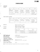
TS-440S SPECIFICATION S (GENERAL ) Transmitter frequency range : Receive frequency range : Mode : Antenna impedance : Power requirement : Power consumption : RX no signal input : TX : Frequency configuration : RX unit : TX unit : (A1,A3J,A3,FSK ) (F3 ) 160m BAND 1 .8 — 2 .0MH z 80m BAND 3 .5 — 4 .0MH z 40m BAND 7 .0 — 7 .3MH z 30m BAND 10 .1 — 10 .15MH z 20m BAND 14 .0 -- 14 .35MH z 17m BAND 18 .068 — 18 .168MH z 15m BAND 21 .0 — 21 .45MH z 12m BAND 24 .89 — 24 .99MH z 10m BAND 28 .0 — 29 .
TS-440 S SPECIFICATIONS (RECEIVER ) Sensitivity : Freq . Mode 100 -- 150kHz 150 500kHz 0 .5 -- 1 .6MHz 1 .6 -- 30MH z SSB,CW,FS K (SIN10dB) Less tha n 2 .5µV (8dBA1 Less tha n 1µV (OdBA ) Less tha n 4µV (12dBA) Less tha n 0 .25µV (— 12dBA ) AM (SIN 10dB) Less tha n 25µV (28dBp) Less tha n 13µV (22dB A ) Less tha n 40/,cV (32dBA) Less tha n 2 .5µV (8dBA ) Less tha n 0 .
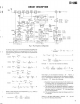
TS-440S CIRCUIT DESCRIPTIO N 1 . Overview • The TS-440 is a triple conversion type transceiver, incorporating a general coverage receiver, which uses 45 .0 5 MHz as the first IF, 8 .83 MHz as the second IF, and 45 5 kHz as the third IF . • The TS-440 is compact, but allows for installation of a n optional internal automatic antenna tuner operating in th e amateur band from 3 .5 MHz to 28 MHz and enables a wide range of antennas to be used .
TS-440S CIRCUIT DESCRIPTIO N ANT 30 K 30MHz 3rd MI X 2nd MIX 1st MIX DET D / 6 .22MHZ \ FM MOD HI I P 5 KHZ 120KHZI D I 1= 1800 1=450 1 J=72441=1811 1 CA R I I FM I I/1 1/1 0 IPLL 5 1 AF OU T AMR,FM R AMT, FMT USB, CW LSB, FSK : 455 KH z : 456. 5 : 453 . 5 MIX 5 4 .55MH IX 4 IPLL 58.25-u 53.25MHz IPLL I p,D I/N,I/A--L --- - 1/450 Y INT=13-.
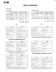
TS-440S CIRCUIT DESCRIPTIO N I=1800, J=7244, K=19800, L=3239, M=4 1 fin = 0 .388 fsTD 1 1 When fIN = 30 MHz (USB mode) in formula 10 , f IN an d fSTD have the following relationship : I = 1800, J = 7244, K = 19800, L = 3239, M = 7 3 .' . fIN = 0 .833 f STD 12 Since the precision of the reference crystal oscillator use d in the TS-440 is 10 ppm (—10 to 50°C) and the receive r system has the characteristics shown in items i) and ii), th e total accuracy is stable at any point from 30 kHz to 30 MHz .
TS-440S CIRCUIT DESCRIPTIO N t Signals from the ANT pin are fed into the RAT pin of the R F unit via the transmit/receive switching relay . The signals the n go to the 10 BPFs through the approx . 20 dB attenuator circuit, the first stage of the first IF trap circuit, and the lo w pass filters (which pass only 500 kHz or less) . The signal the n goes through the second stage of the first IF trap circuit, an d is mixed with the VCO signal and converted into the first I F signal of 45 .
TS-440S CIRCUIT DESCRIPTIO N Filter selective MANUAL MODE AUTO MODE OPTION INSTALLE D WITHOUT OPTION WITHOUT OPTION MODE 8 .83MHz 455kHz 8 .83MHz 455kH z SELECT SSB Through CFI XF1 CF 1 CW Through CF1 XF2 CF 1 N M1 AM Through CF2 Through CF 2 M2 FSK Through CFI XF2 CF I W FM Through — Through — 8 .83MHz OPTION INSTALLE D 455kHz 8 .
TS-440S CIRCUIT DESCRIPTIO N 2) AF notch circuit R OH M BX7I91— 851 8 123 10 BX719 I R7 IOK OUT! - R9 22K SC 5 10 + 0 iI t i U W U D27 D2 6 Fig . 5 NOTCH circui t The hybrid ICI in the IF unit is an audio notch circuit . Figure 5 shows its equivalent circuit . This circuit forms statevariable band pass filter, also known as a bi-quad filter . Th e notch frequency can be changed using the notch control vari able resistor .
TS-440S CIRCUIT DESCRIPTIO N 3 . Transmitter Circuit Descriptio n D Q44 IC4 MIC pPCI I58HZ
TS-440 $ CIRCUIT DESCRIPTIO N DSB by IC4 goes through the SSB transmit switching diode s D17 and D18, filter switching diodes D14 and D12, and SS B ceramic filter CF1, to obtain the SSB signal . The SSB signa l then goes through the transmit switching diode D36 and i s fed into the transmit first mixer, IC6, where the SSB signa l is mixed with the output from the 8 .375 MHz oscillator i n the IF unit, and converted to 8 .83 MHz .
TS-440S CIRCUIT DESCRIPTIO N waves changing from continuous waves to relatively low dut y pulses . Q1 is driven by this voltage waveform to control Q2 , which is connected to the collector of Q4 in series and motor drive voltage is generated . If the motor turns too fast, the SWR value will be smalle r than the motor stop value because of the inertia of the motor .
TS-440 S CIRCUIT DESCRIPTIO N Vs F is compared with voltage from IC8 pin 6 (5 .5 V) . When SWR increases, VSF lowers and the voltage leve l of IC8 pin 8 rises . At IC7 pin 3, a triangular wave is moni tored . The triangular wave is compared with the wav e from IC8 pin 8 and output . The triangular wave is converted to a square wave by IC10 and sent to switch Q 3 and Q4 . This voltage is used as the SWR control voltage .
TS-440S CIRCUIT DESCRIPTIO N FULL BREAK-I N H A L B L C 1 KEYING I N L H D KEYING OU T L H E F L L G L H H CONTROL OU T L SEMI BREAK-IN, VO X A KEYIN G IN VOX L H CONTROL OU T L F L KEYING OU T VOX H J Fig . 9-3 FULL/SEMI BREAK-IN timing char t The above timing charts show the timing for standby an d keying signals .
TS-440S CIRCUIT DESCRIPTIO N 4) Speech processo r IC4 in the IF unit functions as the first stage microphone am plifier or audio speech processor . When the processor switc h is off, IC4 functions as a 20 dB microphone amplifier . Whe n the processor switch is on, IC4 functions as an up to 40 d B gain amplifier with ALC . When the processor switch is on , 8 VDC is supplied to the base of the gain adjustment switch ing transistor, Q41, driving the feedback amplifier .
TS-440S CIRCUIT DESCRIPTIO N VCO I A 45 .08. . 52 .55 MHz 8 52 .55 ... 59 .55 MH z C 59 .55 . . 67 .05MH z D 67.05 ., . 75 .05MHz 2502668 25C266B 555 A A .LPF vco 1 i I BUFF 2SC2458 2SC2668 PLL II 8.5539 .05 MH z ICI4 6.5-.36 .5MH 030 \ 029 2SC2668 2502668 03 8 SN169138 30.175-30.675M H SN15913 P 024 BUFF 2502668 5.82 5 5 32 5 Q27,2 8 02 3 BUF F 2S 0266822 Q3 6 SNI6913F 250266 8 6 14 7 Q22 BUFF 2SC266 8 IC 13 Di v 4 SN7RS,12 N 020 54460L 58 .25-53 .
TS-440S CIRCUIT DESCRIPTIO N ( into pin 2 of MIX5 IC7 (SN1 691 3P) via the LPF . In MIX5 , the signal is mixed with the signal generated by PLL4 an d goes through the BPF to generate a signal in the range o f 6 .53 MHz to 6 .6301 MHz (in 100 Hz steps) . The generated signal is supplied to pin 5 . The 9 MHz reference frequency signal is supplied to pi n 1 of IC17, where the signals are divided by 18 to generate a 500 kHz signal for frequency comparison .
TS-440S CIRCUIT DESCRIPTION pulses and U/D signals from two clock signals which are 90 ° out of phase with each other, and sends the pulses and signals to the 7800 . A clock pulse interrupts the 7800 and a U/D signal causes the 7800 to perform a count up or dow n operation for each step . If fast rotation occurs, the 780 0 processes several steps of PLL data at one time . Voltages from the RIT and IF shift VRs are converted fro m analog to digital by the A/D convertor IC (4052) and fed int o the 7800 .
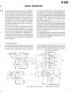
TS-440S CIRCUIT DESCRIPTIO N 1 . Encode r The TS-440S uses an optical encorder . Two different cloc k signals from the encoder are 90°, out of phase with eac h other . This phase difference is not adjustable but depend s on the precision of the module . The two clock signals are converted into clock pulses (250 pulses/rotation x 4) and U/ D signals indicating the direction of rotation by the 4011 an d 4030 and fed into the 7800 .
TS-440S CIRCUIT DESCRIPTIO N 2 . Digital displa y FIP digit and segment signals are driven by the 6300 bu t decimal point and red character signals are driven by a tran sistor . 8 V is used to increase the brightness of red charac ters . The 7800 sends display data serially at 1 MHz, but th e clock signals are divided by two (500 kHz) in the 4080 an d fed into the 6300 . Figure 16 shows how the frequency divi sion is accomplished .
TS-440 S CIRCUIT DESCRIPTIO N 4 . Static input 7800 (ICI ) CO C2 07 "H" when U P "L" when unloc k A/D convertor dat a Encoder U/D signa l Unlock signa l 4052 (IC : Display) 8255 (IC53 ) BO B2 B3 B4 B5 B7 2 9 --%--- 1 AK L DO "L" "L" "L" "L" "L" "H" Lock switc h AT switc h MIC UP switc h MIC DOWN switc h PTT switc h VS-1 busy signal when switch o n when switch o n when switch o n when switch o n when switch o n when VS-1 busy A/D converter Inpu t Fig . 17 A/D convertor circui t 6 .
TS-440S CIRCUIT DESCRIPTIO N 10 . PLL output bloc k PES ,uPD7800 The PLL output block controls five PLL loops . The 500 kH z step PLL loop uses an MB87006 and the other PLL loops us e MN6147s . The M387006 has two dividers : one for the PLL referenc e frequency and the other for a swallow type counter . Frequen cy division data for the reference frequency is sent only on e when the TS-440 power is switched on . The MN6147 uses the PLL data format shown figure 19 . Fig .
TS-440S CIRCUIT DESCRIPTIO N I Band information 7800 PBo — 3, B3B2B1B o 13 . Band information generation circuit (in the R F unit ) Band information from the control unit is sent to connecto r 15 of the RF unit . Band information signals BO to B3 for m a BCD code in which BO corresponds to LSB . Q4D (M74LS145P) is used to convert data from BCD to DEC, an d it generates control signals for ten of the 11 bands . Contro l signals for the remaining band (25 .
TS-440S CIRCUIT DESCRIPTION 14 . Mode control signals Transmit/receive mode signals are generated by ICI 0 in the IF unit . IC 10 is a hybrid IC containing five pairs of PNP transistors and diodes . Figure 22 shows its equivalent circuit . When the mode signals SSB, CWB, RYB, AMB, and FMB are applied to pins 6 ~ tt LL LL 4 to 10, the voltages of control pins 16 and 17 change . During reception, these signals change to SSR, CWR, RYR, AMR , and FMR .
TS-440S CIRCUIT DESCRIPTIO N t 16 . Semi-self test functio n a. Approximately threshold level inpu t b. Incorrect input due to input pin faul t Semi-self test is started by turning the POWER switch o n with the 4 (AM) and T-F SET switches pressed . This test provides a method of testing the TS-440 digita l system in a shorter time during production or servicing . Th e test enables the following : Operation procedure 1 . POWER SW OF F 2 .
TS-440S CIRCUIT DESCRIPTIO N SW Monitor Display changes by TEST numbe r Displa y TEST NO I / I I LOCK 43 I AT 11 I I I / I MI C MI S PT T VS- 1 UP DOWN or Al BUS Y VirU VOIC E LSB tl ► \' RIT A/ B ® SCAN SIT SPRI T 09 rUIN T-FSET A=B USB CW i D AM CLEAR 1MHz 25L 100 L 200 L 400 L (_) 1? L SOL 35U SO U (Ii) 0 100 U 200U 400 U Lg.
TS-440S SEMICONDUCTO R SN74LS138H (Control unit IC51) Data outputs TRUTH TABL E Input Enable G, x L H H H H H H H H Outpu t Selec t G2 H x L L L L L L L L C x x L L L L H H H H B x x L L H H L L H H A x x L H L H L H L H Y3 Y, Y5 Y6 Y7 H H H H H H H H H H H H H H H H H H H H H H H H H L H H H H H H H L H H H H H H H L H H H H H H H H L H H H H H H H H L H H H H H H H H L Yo H H L H H H H Y, H H H L Y2 Note : 1 .
TS-4405 SEMICONDUCTO R TC4013 (Display unit IC3 ) RESE T SE T 6 DAT A 5-D 3 - CL CL CL S 8 Q R 9- D 2 0 I I - CL S R 0 - 13 0 -1 2 10 CLOCK CL CL TC4040BP (Control unit IC55) QI CLOCK 10C'> RESET Q2 LD OOD--CP _ RO D CP _ RO R CP D R CP D 03 05 06 O © ® ® Q4 0 D CP _ ~-CP - -CP RO R0 R0- CP R 0- DO 012 R CP D Q5)0I I R CP (14)Q10 R CP D (12)09 R CP D (13)08 (4)0 7 TC4069B P (Control unit IC4 ) (TOP VIEW) I 1 28
TS-440S SEMICONDUCTO R e MB4052 PC 5 7~J7 Co CI IF-SHIFT - ® 780 0 Comparato r D PC7 Lam, AI R IT - R O r Ag o ~ D , I Multi _ Comparato r Resistor ple 12 ADC CLK le Not us e L PC 6 8255 (IC2 ) A3 8 bi t RS +5v DA C EX . 2 Regulator v CC I EX.! 2 .5 K 6 S VccI Vcc2 O A .G D.G MB4052 Pin Descriptio n I/O Signal Pin Function s Pin No . 2 3 4—7 Functio n Symbol Pin Name Range expande r input Range expande r output Ex . 2 Ex .
TS-440S SEMICONDUCTO R MB8418-LP20-GRA (Control unit 1050 ) AI O mo o OE1 0 GN D Addres s buffer Lo w decode r Memoria l Alley Symbol Ao—A 10 128 x16 x 8 ,uPD7800 I(1 — II A4 n a .~ 0E0 Address buffe r S I/O gat e column decode r --IT WR I /0 Chip select 1 Chip select 2 WE Write enabl e Vcc Power (1 .5 V ) GND GN D NC .
TS-440S SEMICONDUCTO R MC3347 (IF unit IC2) 2 10K 10K 30K $ 20K 5K 50 K 25 14 15 50K 13 0 20 16 220K 15 K .0K K 17 22K 12 26 15K 470 $50K 15 8 27 5 32 ~52 53 54 506 28 OK 100K 10K I0K 29 10K • 10 K 48 490 5 V 60 9 0 1 44 30 . 31 6 .
TS-440S SEMICONDUCTO R pPC1158H2 R7 Amp . ALC nput l wu Input W N .F.B . Output u u u W GND Vcc ALC Output ALC Input Pin connectio n Pin Function 1 Input 2 Pin _ Functio n 5 ALC outpu t N. F . B .
TS-440S SEMICONDUCTO R t PD8251AC (Control unit IC54 ) Data bus Data bus buffer D7o.DI4 7404 2 .
TS-440S SEMICONDUCTO R APD63000 (Display unit IC1 ) Pin description Pin No . Symbol 1 01 3 015 014 017 01 8 Pin name FI P Segmen t driver I/O Descriptio n High dielectric-strength (40V) output in the Pch open . 0 Corresponds to the output of Q13 — Q1 9 ( 0 13' 019) 7 01 9 8 SO Serial data output pin 9 BI Blanking pin 10 LH Latch pin I Transmits the connects of the serial shift register to the buffe r register at low level, to latch the connects at the rising time .
TS-440 S PARTS LIS T r CAPACITORS CC 45 TH 1H 220 1 2 3 4 5 0 1 0 = 1p F 1 0 0 = 10p F ceramic, electrolyic, etc . 4 = Voltage ratin g 1 = Type 5 = Valu e round, square, etc . 2 = Shape 6 = Toleranc e 3 = Temp . coefficient • Temperature Coefficient P R S T U C L 1st Word Color" Black Red Orange Yellow Green Blue Viole t -80 -150 -220 -330 -470 -750 0 pp m/ C • Tolerance Code C ) '-0 .25 D t0 .5 G ±2 J ±5 Less than 10 p F • Rating voltage \2nd or d C A B 1st word 1 .6 0 1 .0 1 .25 12 .
TS-440 S PARTS LIST SEMICONDUCTOR Re marks Diode N N N N Name 1S155 5 1S13 3 1S258 8 15158 7 1S100 7 1SV53 A 1SV15 3 1SS10 1 1SS9 9 1N6 0 1N444 8 Item Digital Tr Re marks N TR N S31 C BA28 2 MA85 8 US109 0 DAN40 1 N Vari-cap ITT310T E Varistor MV 1 3 MV-5 T MV20 3 Zener diode FET SVO3Y S MTZ 3 MTZ 4 MTZ 6 MTZ 7 MTZ 9 MTZ 9 .0J B .3J C .2J A .5J A .1J B .1J C N Thermistor N Surge absober N UZ 3 .0 B UZ 6 .2B L UZ 9 .
TS-440S PARTS LIS T x New Parts Parts without Parts No. are not supplied . Les articles non mentlonnes clans le Parts No . ne sont pas fournis . Telle ohne Parts No . werden nlcht gellefert . Ref . No . Address New Parts No . Description Parts offtit g. - g- fs Desti nation Re mark s 114 4 gl. TS-44 0 2.
TS-440S PARTS LIST New Parts Parts without Parts No . are not supplied . Les articles non mentlonnes clans le Parts No . ne sont pas fournIs . Telle chine Parts No . werden nlcht gellefert . Ref . No . Addres s New parts # FR Parts No . rP. I~ * 55 56 57 58 59 1E 2f( 1F,IG 1G If, ,s 63 64 65 66 67 313 31 : 3E IS 31 68 69 70 71 72 3C -1i'C 2L 2L V29--0741-24 K2907 5-0 8 4 75 76 2t AA 2L .2E iti 4 -g- HEX DHSS HEX BNF i,S HEX MSS HEX BOSS HEX BNSS (Xi') _, .
TS-440S PARTS LIST x New Parts Parts without Parts No . are not supplied . Les articles non mentlonnes dans le Parts No. ne sont pas fournls . Tolle ohne Parts No. werden nlcht geliefert . Ref . No . Address Ne w Parts 93 93 96 97 98 1 :[ ,2j 11,2 j 1K,I G 2D,1 R 1D T 4: Parts No . a it Desti - Re natio n mark s it MI Description X53–1450–1 t X53–1450–2 1 X54–1970-iU X57–1150–0 0 X60–1300–00 14 / .1i.
TS-440S PARTS LIS T New Part s ) Parts without Parts No . are not supplied . Les articles non mentlonnes dans le Parts No . ne sont pas fournis . Telle ohne Parts No . we-den nloht gellefert. Ref . No. V Address New Parts f i% Description :1 -g- Destination / It M[ ::22 MC24 MC25 MC27 MC28 E400673-05 E40-0373-0 E40-5069-05 E40-324I-05 E04-0154-05 PIN CONNECTOR (MINI,6P ) PIN CONNECTNR (MINI .
TS-440S PARTS LIS T x New Parts Parts without Parts No . are not supplIed . Les articles non mentlonnes clans le Parts No . ne sont pas fournls . Telle ohne Parts No. werden nlcht gellefert . Ref . No. Address New Parts # it -q. .6 Parts No. a it Destination Description It * 2502458Y Re mark s A 64 TRANS I STO R RF UNIT (X44-1680-00 ) c 0 C3 14 I:::6 CC45SL 11-1390 j CC45SL JJ-11.21 j CC45RHIH330J CK45F*I .EI473Z C91-1.008-05 CERAMIC CERAMIC CERAMIC CERAMIC CERAMIC : 39PF 1 .
TS-440S E PARTS LIS T New Parts Parts without Parts No . are not supplied. Les articles non mentionnes dans le Parts No . ne sont pas fournis . Tolle ohne Parts No . werden nIcht geliefert . Ref . No. Address New Parts No . Desti - Re natio n marks ft tp7 Descriptio n Parts It FIN it 42 4t * / C59 C6C) C:61 C:62 C63 CE04W 1.801 OM C91-1008-05 CK45131H681K 00453L 1E1151 j 4513 1 I-1152K ELECTR& CERAMIC CERAMIC: CERAMIC:: CERAMIC 1 . OUF 0 . 022UF 6E30PF 1 .
r TS-440S PARTS LIST New Part s Parts without Parts No. are not supplied . Les articles non mentionnes clans le Parts No . ne sont pas fournis . Telle ohne Parts No . werden Net-it gellefert . Ref . No . Parts No . Address New Desti - Re natio n mark s ft lu7 Descriptio n Parts # g A6 / 3R * C1.21 C1.22 C123 C1.24 1:125 C91.-0117-05 CC:45SL 1H470j C:91-0769-05 CI A .5SL 1H 100D C91-01.17-05 CERAMIC CERAMIC CERAMIC : CERAMIC CERAMIC : OIUF VET' 0 . 01.UF 10PF 0 .
TS-440S PARTS LIST New Parts Parts without Parts No . are not supplied. Les articles non mentionnes clans le Parts No . ne sont pas fournls . Telle ohne Parts No . werden nlcht gellefert . Ref . No . It Parts No . Destination Description Parts / ft C:189 Cl . 90, 1.91 I:::192 0193 C194 CC45CH 11-1330J C91-0117-05 CE04WIA47011 C91-0769- .05 CC45RI-11.1-1680J CERAMIC CERAMIC ELECTRN CERAMIC : CERAMIC 33FF O . 01UF 47UF 0 .
TS-440S PARTS LIS T New Part s Parts without Parts No . are not supplied . Les articles non mentlonnes clans le Parts No . ne sont pas fournls . Telle ohne Parts No . werden nlcht ge rlefert . Ref . No . Address New Parts Parts No . :1 f J Jl J2 J3 .
TS-440S PARTS LIS T New Part s Parts without Parts No . are not supplied. Les artIcles non mentlonnes dans le Parts No . ne sont pas fournls . Telleohne Parts No . werden nig ht gellefert . 46 Ref . No . t IR .g. Addres s Ne w Parts IA Parts No. Descriptio n g5 A5 / *A. 1 2 L53 L54 L5 L56 ' 57 L40-3982-14 L40-2282-14 L40-3982-I4 L401021-13 L40-1092-14 SMALL FIXED INDUCTOR(O .39UH ) SMALL FIXED INDUCTOR(O .22UH ) SMALL FIXED INDUCTOR(O.39UH ) SMALL .
TS-440S PARTS LIS T New Parts Parts without Parts No. are not supplied . Les articles non mentlonnes dans le Parts No . ne sort pas fournis. Telle ohne Parts No . werden ni g ht geliefert. Ref . Addres s New Parts N 06 Desti natio n it Descriptio n A A$/ COIL I- OfL {031i 1.19-0362--0 5 L34-229{1-0 5 L34-2277-0 5 L34-2278-0 5 1....19--0344--0 5 BAUM TRANOFORMER(TX DRIVE ) {01L (VCO,HH .
TS-440S PARTS LIS T New Parts Parts without Parts No. are not supplied . Les articles non mentlonnes clans le Parts No . ne sont pas fournis . Telle ohne Parts No. werden nlcht geliefert. Ref . No . V. RR Addres s New Put s Part J L11. f Parts No . a; D3O --3 3 D34 --3 7 D3 8 D3 9 D4 O p GF Descriptio n g 7 oQ Y C ~g / ML a, 7Ti 13158 7 MA85 8 MA85 8 15 :8] .3 3 BA28 2 DIOD E DIOD E DIOD E DIOD E DIOD E MA85 8 MA85 8 ) :TT31OT E MA85 8 ITT31OT E DIOD E DIOD E VOLTAGE VALIAVLE LAP .
r TS-440S New Part s Parts without Parts No . are not supplied. PARTS LIS T Les articles non mentlonnes dens le Parts No . ne sont pas fournis. Tolle ohne Parts No. werden nicht gellefert. Ref . No . Address New Parts No . Description Destination Parts # .REt -gi C2 C3 C4 C5 CO tt f a6 -g- / # 4t CK45FIH103Z CK45FIH223Z CK45BIH102K CK45FIH473Z CK45FIH223Z CERAMIC CERAMIC CERAMIC CERAMIC CERAMIC 0 .010U F 0 .022UF 100OPF 0 .047U F 0 . 0221 E [11. C12 .
TS-440S PARTS LIS T New Part s Parts without Parts No . are not supplled . Les articles non mentlonnes dans le Parts No . ne sont pas fournIs . Telle ohne Parts No. werden nlcht gellefert . Ref . No . Address New parts Parts No . # fig g / * 1 ,1 _ 2M VV WW Y Z JM 1N .2 N 2N N09- 065E3-0 4 N09-0372- 0 4 N09-0682- 0 4 N30-300B-4 6 N30-4005-46 v. SCRE W 5i - FREW PUL LEY ) SCRE W RAN HFAD MACHINE SCR K W PAN HEAD MAi .H[NE SCRE W RL 05GF2-13R W Rc 058E21-1181. f R514AD3A5R6 j RL05GF21-1.
T TS-440S PARTS LIS T New Parts Parts without Parts No . are not supplied. Les articles non mentlonnes dans le Parts No . ne sont pas fournis . Telle ohne Parts No . werden nIcht gellefert . Ref . No. Address Ne w Parts Parts Parts No . Desti natio n Descriptio n ft / gl. C28 C29 C30 C31 L33 CK45131H391.K C91-0769-05 C91-0119-05 C91-011.7-05 CC45SL 1H390j CEfRAMIC CERAMI I CERAMIC CERAMIC CERAM iC 3 r-20FIF D . 01U F O . 047UF O . 01IJF 39P F K K CC45SL 1E-1820j ,39 C91- 011 7-05 n:i.
TS-440S PARTS LIS T New Parts ) Parts without Parts No. are not supplied . Les articles non mentlonnes dans le Parts No . ne sont pas fournis . Telle ohne Parts No . werden nlcht gellefert . Ref . No. Address Ne w Parts Parts No . # 52 Desti - Re nation mark s 1A Descriptio n / C:95 C96 , 97 C98 C:99 CIOO C:91-0 :C 17-05 CC45C-3L.1H 100D C91-0117-05 C91 .--076`-)--0`.'; C:91. -01.19-05 CERAMIC : CERAMIC CERAMIC CERAMIC CERAMIC O . 01UF I.OPF O . 01.LJF 0 . C) I LIE (3 .
TS-440S PARTS LIS T New Part s Parts without Parts No . are not supplied . Les articles non mentlonnes dans le Parts No. ne sont pas fournls. Tells ohne Parts No . werden nlcht gellefert . Ref . No . Addres s Ne w Parts No . Desti nation Descriptio n Parts #ffiiit* fit f A5 41/ IA 64 C178 C179 0180 C181 0182 0S15EIVORIM CK45BIH182K CE04WIHIOOM C91-0117-05 CS15EIVR47M TANTAL CERAMIC ELECTRO CERAMIC TANTAL O . 1UF 180OPF 0 .01UF 0 .47UF 35W V K 50W V K 35W V C183 1184 11 .
TS-440S PARTS LIS T New Part s Parts without Parts No . are not supplied . Les articles non mentlonnes Bans le Parts No . ne sont pas fournis . Telle ohne Parts No . werden n1cht gellefert. Ref . No. Address New Parts No .
IS-440S PARTS LIS T New Part s Parts without Parts No . are not supplied . Les articles non mentlonnes clans le Parts No . ne sont pas fournis. Telle ohne Parts No . werden nicht geilefert . Ref . No . Addres s New Parts No . Part s V ifA f n5 Descriptio n a Desti - Re natio n marks it f'.-J t IC I 4 IC S 11 6 IC7 , 8 IC 9 MN6147 C M54460 L SN74L590 N 5N 16913 P MN614 7 IC(FREO SYNTHESYZER FILL ) I(PRE SCALER ) IC I(DI .JBEE DALANCED MIXER'S ) IC ICI O JCIJ .
TS-440S PARTS LIS T New Part s Parts without Parts No . are not supplied . Les articles non mentionnes clans le Parts No . ne sont pas fournls . Telle ohne Parts No. werden nicht gellefert . Ref . No. Address New Parts No . ) Destination Description Parts # 24 / ft C47 C:51 C52 C53 C54 CK45FlH223Z CM93D2H152j CM9302H471j CM93D2H152j CM9302H221j CERAMIC MICA MICA MICA MICA 0 .0220 F 1500PF 470FF 150OP F 220PF C55 C56 CST C58 .
TS-440S PARTS LIS T t New Part s Parts without Parts No . are not supplied. Les articles non mentlonnes clans le Parts No . ne sont pas fournIs . Telle cline Parts No. werden nicht geliefert . Ref . No. # Addres s Ne w Parts it Parts No . 08 0~, it a6 ,g. L34-3154-0 5 L34--3156-- .0 5 L.
TS-440S PARTS LIS T ) x New Part s Parts without Parts No . are not supplied . Les articles non mentlonnes dans le Parts No . ne sont pas fournls . Telle ohne Parts No . werden nIcht gellefert. Ref . No. ppg g # Sti -4 Parts No . A5 7 PG Desti - Re natio n mark s 11 Wl 'S Descriptio n A5 / ML PG I 'IC L22 C23 -38 C39 -41 C45 -40 ":50 1_90-0022-05 L91-0769-05 L91-0753-05 C;91 .--[1769--0`_i L91 -0119-05 ELELLRN CERAM1C CERAMrL CERAM' CERAMIC- 47LIF 0 .01UF 470PE O . [710F 04 71 ..
TS-440S PARTS LIS T New Parts Parts without Parts No. are not supplled . LesarticlesnonmentlonnesdansleParts No .nesontpasfournls . Telleohne Parts No .werdennlchtgellefert . Ref . No . Addres s New Parts No . Desti - Re natio n mark s ft A fhM Descriptio n Parts Ni D81 082 °s f'1 oS d~, * g).
TS-440S PARTS LIS T New Part s Parts without Parts No . are not supplied . Les articles non mentionnes clans le Parts No. ne sont pas fournls . Telle of-re Parts No. werden nlcht gellefert . Ref . e No . Addres s New Parts No . # Desti - Re natio n mark s it 1(7'11 -lk Descriptio n Parts / itt A S5 3 S5 4 -5 6 55 7 S5 8 -6 0 S31—2405—0 5 S40—2440—1 5 S40—2441—1 5 S40—2440—1 5 SLIDE SWITC H PUSH SWITC H PUSH SWITC H PUSH SWITC H DI -4 D5 ,6 D5 0 ,5 1 D5 2 IC I 15155 5 MT -M .2j A 1.
TS-440S PARTS LIS T New Part s Parts without Parts No . are not supplied . Les articles non mentlonnes clans le Parts No . ne sont pas fournls. Telle ohne Parts No . werden nlcht gellefert . --Ref . No . Addres s New Parts No . Descriptio n Parts 'f ]lid '4 tt _ 115 A * -g- Al; A t / L92–0103–05 L920119–05 L39--0416--05 L39–0415–05 L40–1011–13 TROIDAL CORE (FOR L1 .2 ) TROIDAL CORE (FOR T100,101 ) COI L COI L SMALL FIXED INDUCTO R Li LI3 .
TS-440S PARTS LIS T ) x New Part s Parts without Parts No . are not supplied . Les articles non mentlonnes clans le Parts No. ne sont pas f ournIs . Ta p e ohne Parts No . warden nicht geliefert . Ref . No . Address New Parts No . part s fg *% g5 A It Description Desti - Re nation mark s 1± 107 ,4-$ SIDE TONE UNIT (X59-1060-00 ) -V3E131E223 k 1:1<73FBIF-11231i ck -7 --iFEitE227il< C.HfP c CHIP C CHIP E:23--04 7 1--0 5 TERM INA L .
TS-440S PARTS LIST New Part s Parts without Parts No. are not supplied . Les articles non mentlonnes dans le Parts No . ne sont pas fournis. Telle ohne Parts No . werden nIcht gellefert. Ref . No. Address New Parts No . Desti - Re nation mark s F] Descriptio n Parts V N 5 A / 4 IF UNIT (X60-1300-00 ) C91-0769-05 CC45SLIH150j C91-0769-05 CC45SLIHI5Oj C91-0769-05 CERAMIC CERAMIC CERAMIC CERAMIC CERAMIC 0 .01UF 15PF 0 .01UF 15PF 0 .
TS-440S PARTS LIS T New Parts Parts without Parts No . are not supplied. Les articles non mentlonnes dans le Parts No. ne sont pas fournis . Telle ohne Parts No . werden nicht geliefert . Ref . No . Addres s New Parts No . Desti - Re natio n mark s it 6 4 it Descriptio n Parts tv it -g- 64 Mt it / g- C82 -84 C85 086 ,07 C88 089 C:K45BIH102K C90-2022-05 C:91-0119-05 0045SL 1H120J C092MIH152K CERAMIC ELECTRN CERAMIC CERAMIC MYLAR MOORE 15UF 0 . 047UF 12P F 1500E17 K I. 6W t.
TS-440 S PARTS LIS T New Parts Parts without Parts No . are not supplied . Les articles non mentionnes clans le Parts No . ne sont pas fournis . Tells ohne Parts No. werden nlcht gellefert . Ref . No . Addres s Ne w Parts No. Descriptio n Parts # 51t A * A Desti natio n ft / 0150 [151, 152 0153 I:154 . 155 C156 17-05 C91-0119-05 CC45SL 1H470J C91-0 119-05 CCA. 5SLIiEll.E30J I'ERAM C CERAMIC CERAMIC CERAMIC: CERAMIC 0 . 01UF O. 047UF 47PF 0 . 047UF 18PF K K J K j 0:158 .159 0I.
TS-440S PARTS LIS T New Part s Parts without Parts No . are not supplied . Les articles non mentlonnes clans le Parts No . ne sont pas fournls. Tolle ohne Parts No. werden nicht gellefert. Ref . No . Addres s New Parts No . Descriptio n Parts it 4t Ml it / E40-0773-05 E40--0h3--05 E40-1073-05 PIN C .
TS —440 $ PARTS LIS T New Parts Parts without Parts No . are not supplied . Les articles nonm msAe >~A No . ne sont pas @u & A» oh mANo_±mnht a~Ue± Ref . No. # m# f Address New £ P, § Parts No . team Description nation A A x # D35 q6 D37 ,30 S9 D40 1N60 151587 131555 1N60 151555 DIODE DIOD E DIODE DIOD E DIODE k1 042 ,43 D45 ,46 047 D48 ,49 ISS133 IN60 I 133 MI204 155133 DIOD E DIOD E DIOD E DIOD E DIOD E DSO I D52 2 D53 3 ,54 D55 151587 MTZ9 .IJB Y06B ISI587 MTZ6 .
TS-440S PARTS LIS T x New Parts Parts without Parts No . are not supplied. Les articles non mentlonnes dans le Parts No . ne sont pas fournis . Teile ohne Parts No . werden nIcht gellefert . Ref . No . Address New Parts No . Description Parts 0, RI it pa * AIS / 021 11122 023 .
PC BOARD SWITCH UNIT (X41-1610-00) TS-440S Component side view 2 • F d 4 45 A 38W 88 S 45S HV W 88C AU T o – w RX B m I GN D 1, 2SD1406(Y ) 2SC2458)Y ) DTC114ES v v N 6 2SK30(GR ) IC1 : AN7808, IC2, 3, 6 : AN7805, IC4 : LM2931Z-5 .0, IC5, 8 : NJM2904S, IC7 : NJM2903S, Q1 : DTC114ES , Q2 : 2SD1406(Y), Q3, 4 : 2SK30(GR), Q5, 6 : 2SC2458(Y),D1 : 1S1555, D2 : MTZ7 .
TS-440S PC BOARD VIE W Component side view FILTER UNIT (X51-1340-00) 000 PW M AL M RX B RX B RX B 2 5A V 5A NC AL C NC 14 S 2SC 181 5IY1 TXB B 2SC311 3 DTC114E S 4 ^ O--\.QQQl-"—O 0v OI 0O O O — tiQQ4_ 1Ov r-8---O O Th O L_ O1 O ^ O I q S NilY^' -4* L3 9 L38 0 c us C36 016 C v O I " C41p q O 2J4 14109 ;l T h I _of 6 1 0 J 0 O 1=--0 ccE=t= X51-1340-00 L L f- .I 4_4_ m J Q! VI r r r r IN IN N 0 G W r, r nl I .
FILTER UNIT (X51-1340-00) 10 2 DI 2 -1 D011'' .--.—, Tl ,11 L1. I L Tl 2' — Tl ICI ~M '21 'I J5 8 520 . n--,—, TI Tl °~ =11 :. I J 1 'D 01 .4 .6 02 03 05 DT C1142 $ .2551815 Y 25C3113 8 86718 I .05 D I D 2 D 3- 5 D 6.8 0 7,2 5 D 01 0 D 12-23 D 28 r7t'IGI J .81 8 /8.- 15158 7 15,007 15510 1 M728 .IJC o, U3-5 .181.. .TZ7 .5JA .728.3JC .723.
TS-440S PC BOARD VIEW PLL UNIT (X50-2050-00) Component side vie w 250 1959 IYI R13 8 C169 C14 4 m o 2 1 ~ ; Rl_t4^C 1 L30 0 IgIF 0 R139 84 3 D C173 --- - R12 ~" "~'1"v mR124 C159 C111 t 3 I( _ + C10 4 n 89 R130 N I "L3 022 ~-: ~-~8 tJ ^ R92 E ~I _ ~J TP L34 E030 V- CI61 _ C1 1 0 R93 f ,w 0 TP8 i O- 3ND 9 ?B-t:-±_ 0 C133 0131 2SC3113 (B ) 2SC2458 )Y ) -I C132 E B 2SC2668 )Y ) 1146 LO 2SC2787 (LI C11 2 L27 .
TS-440S DISASSEMBLY 45x2 17 Lx 2 Lx 2 J M3x6 L M3x6 P 03x8 (F) Ni (BI) Ni (Br-Tap)Ni N33-3006-4 1 : N35-3006-4 1 N87-3008-41 TS-440(A/8) Parts with the exploded numbers larger than 700 are not supplied .
TS-440S DISASSEMBLY C (X60-1300-00 ) (X50-2050-00 ) f 1 72x 3 71x 4 64 0 GND SEMS G M3x4 H M3x4 M 02 .6x6 N 03x6 T M3x6 (F) (F) (Br-Tap) (Br-Tap) (6)) N09-0256-0 5 : N09-0699 - 05 : N32-3004-4 6 : N 32-3006-4 6 N67-2606-4 6 : N87-3006-4 6 : N35-3006-46 MX4 S2 2 8) M x2 TS-440(B/8 ) Parts with the exploded numbers larger than 700 are not supplied .
0 0 9 tI 55x2 / C Fx2 H , (X41)(L/I4 ) \~0 co (X41)(D/14 ) N C 88 .
TS-4405 DISASSEMBLY o • a v. o o o o 0 ocDCo o N N M x o n o OM M Z Z Z ~ • 3 Nx 0 Parts with the exploded numbers larger than 700 are not supplied .
TS-440S DISASSEMBLY 88 E M2 .6x8 Ni M 02 .6x6 (Br-Tap) N 03x6 (Br-Tap) R 03x10 (Br-Tap)Ni N30-2608-4 1 : N87-2606-4 6 N87-3006-46 : N87-3010-41 (X41-1610-00 ) 88 (C/14) TS-440(E/8) Parts with the exploded numbers larger than 700 are not supplied .
TS-440S DISASSEMBLY l m co x pp In M < 0 <000)- N Z K x X Parts with the exploded numbers larger than 700 are not supplied .
TS-440 S DISASSEMBLY Parts with the exploded numbers larger than 700 are not supplied .
TS-440S PACKING T 23 24 81 26,27, 28,30 , 31 , 66,8 4 40 37 41 38 / 39 36 r0 3 34,3 5 TS-44 0 Part s with the exploded numbers larger than 700 are not supplied .
TS-440 S ADJUSTMEN T • POWER I l VJICE NB 00 a , nFF s ATT E 74 ALL PWR SWR ~— 0 ..R =0 HF TRANSCEIVER MODE I, I ~LSR I' r I USfi I o P CW o cE - 55 oE m150 .N 5 SW' q 7 \\\\\\III1/////e I KEN WOODITS . 440sl _ENO !! l I 11 . I ! 1 /. ON HP I , I-1 I O O I 0 1v ~rM . IN 0O f I _I I_l ~I il l 11 I] l l 1. 1_I. . 1_ l IJ ~f. ~ I~_ I_l .
TS-440 S ADJUSTMENT 14 . Spectrum Analyzer (SPE-ANA ) 1) Frequency range : 100kHz to 110MHz or greate r 2) Bandwidth : 1 kHz to 3MH z 15 . Detecto r 1) For adjustment of PLL/VC0 BPF OUTPUT 1N60 T loop • 16. Directional Couple r 17. Power suppl y PS-43 0 18. Microphon e MC-60A or MC-42S Q GND • Japanese "SG" – 6 dB 0 dB 6 dB 12 dB 24 dB 30 dB 40 dB 50 dB 60 dB 70 dB 80 dB 90 dB 100 dB 120 dB American "SG " 0 .25µ V 0 .5µV 1µ V 2µ V 8µ V 1 5 .
TS-4405 ADJUSTMENT • VOLTAGE CHECK, ADJUSTMEN T Measurement Item 1 . Voltage Condition 1) POWER : ON Tes t equipment DC V .M Adjustmen t Specification/Remark s Unit Unit ' Terminal IF Part 19 -5 Method Check 13 .3- 14.3V RF GAIN : MAX 19 -9 4 .5-5 .5 V MODE USB 19 -10 7 .2-8 .2 V STBY REC 9 -1 27- 4 SW " A " VR-4 2 .6V IF 8 .8V VR-5 +0 .05V, -OV • COMMON ADJUSTMEN T Measurement Condition Item 1 .
TS-440S ADJUSTMEN T Measurement Condition Item 7 . PLL 62MHz BPF Test equipment 11 MODE AM Readjust T9 (VCO2 OSC coil) to unlock . (Core is fully bottom position) Tracking Gen . 2) Connect 5609 resister in Tracking Gen . output line . Use oscilloscopes probe to connect to spectrum analyzer .
TS-4405 ADJUSTMEN T s • RX ADJUSTMENT Measurement Item 1 IF AM P (common) Condition Adjustment Specification/Remark s Test equipment Unit FREQ 14 .1750MH z MODE US B RF GAIN Control MA X Use the minimum SSG inpu t possible during alignment . SS G Rea r AF V . M Panel Oscilloscope AF dummy load (8S2) 2 . 2nd MI X balance FREQ . 14 .1750MH z MODE US B Connect the SSG to ANT terminal . SS G AF V . M Oscilloscope 3 . 1st MI X balance FREQ MODE 4 . IF TRAP FREQ 29MHz Band SSG 45 .
TS-440S ADJUSTMEN T 0 • TX ADJUSTMENT Adjustment Measurement Item 1 . TX AMPM Condition Tes t equipment 1) FREQ : 14 .1750 MH z Oscilloscope MODE : C W CAR LEVEL control : MA X RF unit VR 4: CENER Disconnect DRV connector from RF unit . Then, connect as shown right . STBY : SEND Specification/Remarks Unit Terminal Unit RF DRV RF 1) FREQ : 14.
TS-440 S ADJUSTMENT s Measurement Item 8 . Carrie r suppression Condition FREQ : 14 .1750 MH z MODES : USB and LS B MIC LEVEL control : MIN STBY : SEND Tes t equipment Adjustmen t Specification/Remark s Power mete r Oscilloscop e or Spectrum analyzer Unit Terminal Unit Rear Panel AN T (Direc tional coupler) IF Part Method I VR 7,8 MIN -40 dB or les s Directional coupler L~ Ts-44o - _ 9 . SSB mad e frequenc y response FREQ : 14 .
TS-440S ADJUSTMEN T Adjustment Measurement Item Condition 2) AT-TUNE SW: OF F Disconnect No. connector from AT unit . STBY : SEN D Set . SWR 1 .25 reading when VF O dial is turned . 3) STBY : REC AT TUNE: ON 4) AF TUNE : OF F Reconnect No. 1 connector afte r adjustment . 96 Tes t equipment Specification/Remark s Unit Terminal Unit Part Method Set as show n right . PWR 0 SWM AT VR2 Adjust VR2 until AT TUNE indicator jus t goes off.
TS-440 S ADJUSTMEN T Item 1 . Rese t check Condition 1) FUNCTION SW : A POWER SW : OF F Set the POWER SW ON while depressing the I A = B key . Then release the IA = B key . 21 FUNCTION SW : B 31 LVFO/M SW : ON M .CH SW : Change the chan nels in 00 through 99 order . 2. Band 1) [VFO/M] SW : OFF 1MHz STEP SW : OF F Depress the "BAND : UP " key once . Press repeatedly . 2) Hold the "BAND : UP " on Operation chec k FREQ : 14,000 .
TS-440S ADJUSTMEN T TOP VIEW VR7 L18 VR 8 L5 L4 L3 TC 1 L2 VR 2 L6 L1 2 VR1 0 VR 9 L1 L1 5 VR1 4 TC 2 VR1 3 VR4 (RF GAIN ) VR5 (RIT ) VR7 IF SHIFT) VR1 VR6 VR3 VR5 98
R96 L21 TP6j ITP51 R6 0 TP 3 L1 3 ITP2 ] R6 4 TP4I T16 VR2 T15 T14 T1 3 R11 2 ITP8I T1 TP11I L1 ITP1 VR14 VR1 3
TS-440S ADJUSTMEN T BOTTOM VIEW VR4 SI VR2 VR 3 T1 0 VR 6 T1 1 VR 3 T1 2 T9 T8 T2 4 T2 3 T2 2 T2 1 T16 T5 T14T13 T6 VR2T15127 T26 100
RX SECTION RF UNI T I4 .2MHz -1 - 8 .83MHz 45 .05MHz OdBp I 40 dB .p F1 CI3 5 —F RI F 7171 I. - IF UNI T 455KHz 45 70 54 94 107 dB,u f : 14 .200MH z X .F INPUT : OdB y AF OUTPUT : 0 .68V/811 o— RIF 44 [FM] CF 3 Frequency : 14 .200 MH z Input : 0 dB u AF input : 0 .68 V, 8 ohm s Note 1 : The SSG signal of 14 .200 MHz, 0 dBu is input from the AN T terminal and the audio output of 0 .63 V, 8 ohms is obtained b y adjusting the AF GAIN VR .
TX SECTION — IF UNIT I KH z 2 .3mV 455 KHz 6 .1 mV .067 V .014V 8 .83 MH z .14V .24V .058V .I IV .017 V CF 4 MIC MI C CAR 455KHz CAR 8 .375MH z .042 V .I6 V (RF —It UNI T FINAL UNI T 45 .05MHz 14 . 2 MH z .6 V .37 V 0-TIF .66V 4.6V I .2V 90V 0 DRV HET 36 .22MH z .27 V VC 0 .76V f : 14 .200 MHz !KHz (FM ) 5 .5mV .019V Frequency : 14 .
2nn OX MIX NB GATE 25 DIS 1 34 2 30'33 SSB,C.,AM M C 8 87M/0 .0 i 7362668 3 2 AM 3=KO'= ''~ IF AMP ' 1^ 35K2 3 N W 65 83M / H • ss s IOPTIONI z 669 n CPT 2s,, 62A 2.7668 3 2 7502668 D52,53 305358z AM P 25C2a56 2502459 D30 8.716 1 BUFF , 2.2456 IF AMP MCP 2SC2459 1166 61 AMP 2.2063 BUFF 25C 65S BUFF 25026. 22 IN TX MI X APIS, SIDE TON E 030 12 AM P BUF F 230458 LP, 556c 11I21 3.
PS-50 ADJUSTMEN T 1 . OUTPUT VOLTAG E 1) Connect the load and set the current to 20A . 2) Adjust output voltage to 13 .8 V±0 .4 V with VR1 . 2 . PROTECTION CIRCUI T 1) 2) 3) 4) POWER SW : OF F Connect a 0 .1 SZ 10 W resistor . POWER SW : O N Adjust VR2 so that 0 .1V DC is obtained .
PS-50 SCHEMATIC DIAGRAMIPC BOAR D SCHEMATIC DIAGRAM (X43-1520-00) 240V Versio n Q4 0 8" D3 3 D6 . Q1 02,3,5 04 D1,6,0 D2,3 D5,7 D4 D8 THi TH2 2SA5621Y ) 2SC2458(Y ) .258761(0 1 .15155 5 U05 B UZ-Q .IB L UZP-1B B 'UZ-15B H 32D27 5TP-41 L DC ~3 .BV ue%~E o L 1 1 T AVR UNIT IX43-1520-00) ~~~~o--.
PS-50 PARTS LIST New Part s PARTS LIST Parts without Parts No . are not supplied . Les articles non mentlonnes clans le Parts No. ne sont pas fournls. Telle ohne Parts No . werden nicht gellefert . Ref . No . Address New Parts Parts No. Desti- Re nation mark s it E47 Description fii / #~ PS-5 0 4: 4: _ - 44 4 -- t -- 4: t - _ 4 T 4i rt C2 CO rtO AOt --1000--02 A01 .--1.001 .--12 A01-tO02 t2 [[(U--2561 .
PSIO PARTS LIS T New Part s Parts without Parts No . are not supplied . Les articles non mentlonnes Pans le Parts No. ne sont pas fournls . Telle ohne Parts No . werden nlcht gellefert . Ref . No . Address New Parts No . vfflit 213 Si S2 I NOT FOOT J2I 4180--0 . J21 4101 1 4 J30 054 04 J42--0403_0 5 J61-0400 0 5 tl9UNfING HARDWARE(FAN ) 110LNV HARDWARE (P . i SPAEL R 1'9W[R 1 ORD HUSHIN G WIRE HAN D 2 Re mark s Sg (R ) (/3 .
PS-50 PARTS LIST New Parts Parts without Parts No . are not supplied . Les articles non mentlonnes dens le Parts No. ne sort pas fournis. Tells ohne Parts No. werden nicht geliefert . Ref . No. R2 R4 R8 RI1 R21 .3 .9 .12 VR1. VR2 DI D2 D4 D5 DO .3 D7 DO D9 01 .3 04 175 TI-11 '1I1r' Address New Parts Parts No. Destination Description RS14Gf33A4R?J RD1.4DE32H121 .J RS14GB3A01DJ f `-31.4G03A331 .3 RS14GI33A1 .31J FL---PROOF RS .;MALL .
PS-430 SCHEMATIC DIAGRAMIPC BOAR D ADJUSTMEN T 1. Connect the load and set the curren t to 15A . 2. Adjust output voltage to 13 .8V ±0 .4V with VR1 . RE D 01,2 2N588 5 01 02 AVR UNIT(43-1440-00 ) 01 Ac C ° 1 Mt ,TEMM D1 02 0 20 A 23 .5 V 16 .5V R2 2 .2 AA, 2WW 1IF-,92 • ci D7 - Q1 2SB512(P) 07 2SA562(Y) LQ2 i,56_2SC1815(Y)_D1,2 _U05B 0 D1 120V 0 . 1 D5 : XZ090 D3,6 1S1555 D7 : MT- 16JA D4 _RD91EB2 _TH1 321)27_ rat 0S 13 8 V VAX '0 A D FUSE 6A T 120V --- :USE A .
PS-430 SPECIFICATIONSIPARTS LIS T SPECIFICATION S Part No . 120/220/240V AC±10%, 50/60H z Input voltage : Output voltage : 13 .8V DC (standard voltage ) 20 A (25% duty cycle) 15A (50% duty cycle ) Output current: Continuous load current: 10 A max . (including external output terminal ) Output voltage fluctuation : Within ±0 .7 V at AC 120V, 220V, 240V±10 % (Load current : 15A ) Within 0 .7 V between 2—15 A load . (No-load output voltage : Less than 16V a t 120V/220/240V . AC ) Ripple voltage .
VS-1 SPECIFICATIONIPARTS LIST/PC BOARD VIE W I SPECIFICATION S Dimensions : W 70m m TALK SPEED SELECTIO N H 15m m Speed is factory set at "standard " talk speed . Three different speeds can be selected . D 35m m Weight : 20 g Note : When placing the jumper, solder carefully . Spee d OUTSIDE VIE W Std . speed 30% more than Std . 60% mor e than Std . Jumper place 1 X X 0 2 X X 0 3 X 0 X Symbol 0 , denotes the place in which a jumper wire i s placed . PARTS LIST Part No .
VS-1 SCHEMATIC DIAGRA M 0 0 0 0 0 0 0 0 J0 2 CI 47 IOV LANGUAG E SELECT ENGLISH IC 1 MN64O1TR A IC 2 AN6562 IC 3 TC4O1O7B P 0 3 SI a-i 2 JAPANESE B 7 6 1 -0 28 27 26 25 24 23 22 21 20 19 18 17 16 1 5 o n a a lJ I 5 IC 3 I 2 3 4 d a a LLa m N > IC 1 g o D o o w 23 4 N 5 6 o m 7 8 9 0 11 6 .
MB-430/SP-430 SPECIFICATIONSIPARTS LIS T MB-430 OUTSIDE VIEW MB-430 PARTS LIST Part No . N : New part s Description mks A13-0635-03 N Angl e B50-4016-00 N Instruction manua l H01-4454-03 H25-0077-04 H25-0098-04 J30-0521-04 N09-0007-05 N09-0008-04 N14-0009-04 N15-1060-46 N 16-0060-46 N32-3006-46 N99-0309-04 Ref . No . Packing control (inside ) Protective ba g Protective bag 150 x 480 N Spacer x 2 Wing bolt x 5 Hex .
YK-88S/SN,YK-88C/C N FILTER YK-88S YK-88C Item Ratin g Item Ratin g Nominal center frequency 8830 kH z Center frequency fo 8830 .7 kH z Center frequency deviation Within +150 Hz at 6 d B Center frequency deviation fo+150 Hz at 6 d B Pass bandwidth +1 .2 kHz or more at 6 d B 6 dB bandwidth +250 Hz or mor e +1 .5 kHz or more at 6 d B +2 .2 kHz or less at 60 d B +3 .
AT-440 PARTS LIST New Part s Parts without Parts No . are not supplied. Les articles non mentlonnes Cans le Parts No. ne sent pas fournis . Tel le ohne Parts No . warden nicht gellefert . Ref . No . Address New Parts Parts No . Description Desti nation Re mark s AT-44 0 - . B4E--0411-00 B50--[1054--00 WARRANTY CAR D I:NSTRU[ - [11ON MANUA L I-101--469 5-[]4 HO -3-2283-04 H12--1.390-03 (-112--1397.